I did it, working coil! (and datalog)

Show off your finished kit here!

Re: I did it, working coil! (and datalog)

Postby Freebee » Thu Dec 05, 2013 3:47 pm

I got better parts to fix my primary to. Some plumbing parts are awesome for a tesla coil.

If pictures say a thousand words, a small movie says a book.

  • 230V edition
  • 47nF tank capacitor, instead of default 68nF cap
  • 7 primary windings, close together
  • Secondary resistance: 221 Ohm
  • Primary diameter: over 8.5cm
  • Amp draw @ max: 2.38A

Image

Here's Paranoid with the same setup, at 50% power.

Image

  • 230V edition
  • 47nF tank capacitor, instead of default 68nF cap
  • 6.5 primary windings, close together
  • Secondary resistance: 221 Ohm
  • Primary diameter: over 8.5cm
  • Amp draw @ max: 2.23A

Image

I think the latter has the best performance. I'm really starting to love this thing. Once you're past blowing stuff up, and being careful and precise, there's not much to go wrong. Also, some of the midi files posted in the midi thread are really awesome at larger power levels!
Freebee
Terrific Tube
 
Posts: 50
Joined: Sat Nov 02, 2013 2:27 pm

Re: I did it, working coil! (and datalog)

Postby Freebee » Thu Dec 12, 2013 4:26 pm

My scope arrived!

And it's a gem, never expected it to be so easy. Take it out of the box, install the software plug it in and you're done. Gotta love USB scopes. It's a Hantek6022BE which I got from DealExtreme for about $70. Thanks Speedy87! :D

Here's a screenshot of my secondary output. It's the output on the lowest power setting, with a 20 inch long piece of wire attached to the topload. I've just hung the probe somewhere in the vicinity of the coil. The frequency measured 285.7kHz, although I'm not really sure about the freq. measure function on the software.

Image

According to this I can assume that with 20" streamers, the coil is tuned well? There's a) a quick buildup of charge on the coil, followed by the discharges that take longer to die down. If someone could check whether or not this seems right, it would be very much appreciated.

I'm still far from actually tuning. I'm planning to use a small current transformer on one of the primary feed wires, so I can attach my other probe and measure them both at the same time. I've probably got a toroid core, small wire and a big resistor to make one, so it shouldn't be a problem.

Small steps at a time. 8-)
Freebee
Terrific Tube
 
Posts: 50
Joined: Sat Nov 02, 2013 2:27 pm

Re: I did it, working coil! (and datalog)

Postby Speedy78 » Thu Dec 12, 2013 6:35 pm

If your using the freq mode it qill average both your primary and secondary waveform so it wont work to see both. Thwre is a small icon up top that allows you to drag out a grid from peak to peak or trough to trough on the wave for the primary and then do the same for the ringing secondary (smaller sin wave on the tail of thay image) you can measure from any part of that wave as long as you measure to the exact same point of the next. If you are showing numbers like 600Khz you have not gone far enough to the next wave. If you see real low numbers you have gone to far.
Speedy78
Magnificent MOSFET
 
Posts: 127
Joined: Sun Oct 20, 2013 3:26 pm

Re: I did it, working coil! (and datalog)

Postby Freebee » Fri Dec 13, 2013 11:56 am

I'll try that, thanks for pointing it out. Are there any specific parts of the wave I'd need? Like the ringing up part would seem the part I need, not the ringdown, or doesn't it really matter?
Freebee
Terrific Tube
 
Posts: 50
Joined: Sat Nov 02, 2013 2:27 pm

Re: I did it, working coil! (and datalog)

Postby Speedy78 » Fri Dec 13, 2013 12:10 pm

The larger part of the waveform is your primary, it will overtake the secondary in the graph so you can measure the tall part of it. Then the ring down at the end is your secondary. Measure each separately with the drag out freq measuring tool and you should be able to see where you sit as far as tuning.
Speedy78
Magnificent MOSFET
 
Posts: 127
Joined: Sun Oct 20, 2013 3:26 pm

Re: I did it, working coil! (and datalog)

Postby Freebee » Fri Dec 13, 2013 5:47 pm

Well, did some more testing.

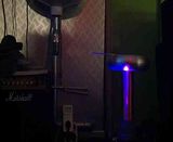
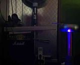
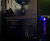
This was my test setup.
Image

Image

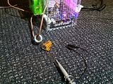
I used the scope and put the first channel probe on a quick made current transformer. I have no idea about the ratio or anything, I just care about the frequency and it does just that! The second probe was open on the ground, just like that. Can't get any easier than this.

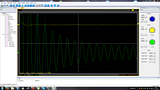
The scope's trigger function is a takes a little getting used to. It might have something to do with the coil's natural pulsed behaviour, and that the waves of oscillations are hard to pick up for this scope, but I've managed to get in the screen by varying the second (sound frequency) knob by bits.

Some data (Have I mentioned I seem to be very bad at measuring streamer lengths?):

  • Setup:
  • Primary tank cap: 47 nF
  • Secondary coil: 221 ohm
  • Breakout: 7 cm out of topload

The frequencies were hard to determine, because if I moved a pixel, the frequency could vary by 5 kHz. I measured the secondary frequencies at the first wave just after the primary stopped, in the ringdown.
Image

(0% power output means that the power knob is at it's lowest setting)

Primary coil: 6,5 windings
Power setting, primary frequency, secondary frequency, est. streamer length
0%, 267 kHz, 324 kHz, 2 cm
10%, 267 kHz, 324 kHz, 2 cm
20%, 267 kHz, 327 kHz,2 cm
30%, 267 kHz, 320 kHz, 11 cm
40%, 267 kHz, 320 kHz,18 cm
50%, 267 kHz, 311 kHz, 34 cm
60%, 267 kHz, 307 kHz, 36 cm
70%, 267 kHz, 307 kHz, 32 cm
80%, 267 kHz, 307 kHz, 29 cm
90%, 267 kHz, 295 kHz, 31 cm
100%, 267 kHz, 301 kHz, 32 cm

Then I went to 7 just for trying. As expected, the primary frequency goes down.

Primary coil: 7 windings
Power setting, primary frequency, secondary frequency, est. streamer length
0%, 257 kHz, 325 kHz, 2 cm
10%, 257 kHz, 329 kHz, 2 cm
20%, 257 kHz, 337 kHz, 2.5 cm

Primary coil: 6 windings
Power setting, primary frequency, secondary frequency, est. streamer length
0%, 272 kHz, 318 kHz, 2 cm
50%, 272 kHz, 311 kHz, 30 cm

Then I tried 5 primary windings, as I figured every half winding was about 10 kHz primary frequency added. That would mean I got to about 285 or 290 kHz primary freq. Very much near the secondary frequency at the big streamer lengths...

Then I got this:
Image

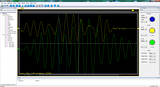
The primary is doing weird things. I've read this and that and might this be because the secondary is putting back energy in the primary? (bucking was the term?) The frequencies vary here, but the clean waves measure about 318 kHz, and the little bits in between are about 250 kHz. The coil operated fine from eyesight, however. Avarage amp draw from mains, and much bigger streamer lengths at lower power.

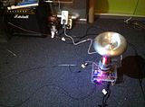
I noticed the same kind of behavior when I tried the large 20" streamer wire attached as in the setup picture.

*edit*
I just remembered that with the lower value tank capacitor, the primary frequency should be higher than what I'm reading...
Freebee
Terrific Tube
 
Posts: 50
Joined: Sat Nov 02, 2013 2:27 pm

Re: I did it, working coil! (and datalog)

Postby loneoceans » Sat Dec 14, 2013 1:12 am

Freebee wrote:I just tried adding more windings on the primary coil. Still waiting for my scope, I saw it has shipped, but... China :roll: I'm flying blind here, I can only vary my windings and check the results in spark length and mains amp draw. I've gone from the original setup posted in the OP here, and changed only the primary windings.

At first I tried 6,5 windings. I've stepped off the huge spreading shown in the previous picture, and instead tried adding half windings.

  • 230V edition
  • 47nF tank capacitor, instead of default 68nF cap
  • 6,5 primary windings, close together
  • Secondary resistance: 221 Ohm
  • Primary diameter: barely 7cm

I got more amp draw from mains, up to 1.9A at 100%. Sparks were about as big as with 6 windings. The sparks stopped growing at about 50% power, only to become a little fatter, but not really much. Seems awfully familiar with my original 6 windings. Probably due to the fact that my diameter has also changed to a smaller size.

Then I went for 7 windings.

  • 230V edition
  • 47nF tank capacitor, instead of default 68nF cap
  • 7 primary windings, close together
  • Secondary resistance: 221 Ohm
  • Primary diameter: barely 7cm

This actually made a noticeable change. Amp draw was larger, but so where the sparks. I think I got the 30cm sparks at 33% power. At 40% they grew even more, but I had to stop there, as the secondary was arcing over to the primary. I think this is actually due to the fact I used a smaller diameter, where the secondary coil is way too close to the primary, and also I used black duct tape, which may contain carbon(?). I used a cardboard tube at first, but that arced over like hell, so I slid a piece of brown PVC over it, which may also contain traces of carbon.

I also probably need to give it a nicer coating of varnish, as the current coating does not hold.

Here's a picture showing the setup.
Image

Also I can totally advise for using sandpaper to sand the toroid while putting it on a spinning drill. Just look at the awesomeness it adds!
Image

I am definitely going to experiment more with more windings. I might buy some length of (non-dark) 80mm or 90mm PVC tube, and make a better primary from that, as the current setup seems holding it back. Also, what would the primary diameter have for effect? More coupling?


Looks like your coil is reasonably well tuned but has too high coupling. I'd try making a large diameter primary with fewer turns; that should work quite well.
User avatar
loneoceans
Magnificent MOSFET
 
Posts: 103
Joined: Mon Feb 11, 2013 12:39 pm

Re: I did it, working coil! (and datalog)

Postby Freebee » Sat Dec 14, 2013 11:56 am

Yeah, I am still worrying about too much coupling. I've been aiming for a 1.15 detuning primary versus secondary. At 320kHz secondary that would mean a 272kHz frequency.

With 6.5 windings I am actually spot on, and the coil behaves well, only the scope plot says otherwise.
Image
*Don't mind the freq. displayed, the primary freq is around 275kHz here, the secondary in the ringdown about 295kHz. I'm at 50% power btw.

This is the corresponding output.
Image
Image

The thick wire I use for the primary is generating too much coupling, I think, and it's loading down the secondary. The wire originally supplied is much thinner, and can be rolled with the same windings much tighter. That's probably were my problem lies.

On the other hand, scoping the thing is much more interesting than I'd thought. I've learned so much of this already. You can really see everything happening in front of you, even without the sparks.
Freebee
Terrific Tube
 
Posts: 50
Joined: Sat Nov 02, 2013 2:27 pm

Re: I did it, working coil! (and datalog)

Postby Freebee » Tue Dec 24, 2013 5:40 am

Seriously?

I apparently fried another 7815 voltage regulator. I was trying to scope the thing true to confirm the pulses. (curiosity got the best of me, and when you have a scope you are ought to use it) I contacted the 15V to the ground for an instant, that's enough to destroy the 15V regulator beyond repair, the same thing I had before. It gets hot to the touch instantaneously, and although it's putting out a regulated voltage, I'm sure it won't handle the operating load anymore.

Now of course I'm out of 15V regulators once again :x . Bah, I wish they could take a beating like the 5V regulators could.

*edit* well it still works. I did a quick Happy Birthday song to sent to a friend, and it held up, but I'm sure that the regulator will start fires, as it gets so incredibly hot. I might try fixing the regulators to the board with screws or anything like that. When things are so prone to breaking I'd rather find them easily replaceable than stuck on the board. They are so annoying to desolder.
Freebee
Terrific Tube
 
Posts: 50
Joined: Sat Nov 02, 2013 2:27 pm

Re: I did it, working coil! (and datalog)

Postby Bayley » Tue Dec 24, 2013 10:52 am

Freebee wrote:Seriously?

I apparently fried another 7815 voltage regulator. I was trying to scope the thing true to confirm the pulses. (curiosity got the best of me, and when you have a scope you are ought to use it) I contacted the 15V to the ground for an instant, that's enough to destroy the 15V regulator beyond repair, the same thing I had before. It gets hot to the touch instantaneously, and although it's putting out a regulated voltage, I'm sure it won't handle the operating load anymore.

Now of course I'm out of 15V regulators once again :x . Bah, I wish they could take a beating like the 5V regulators could.

*edit* well it still works. I did a quick Happy Birthday song to sent to a friend, and it held up, but I'm sure that the regulator will start fires, as it gets so incredibly hot. I might try fixing the regulators to the board with screws or anything like that. When things are so prone to breaking I'd rather find them easily replaceable than stuck on the board. They are so annoying to desolder.


Hrm, the 15V regulator should be internally short-circuit protected; you sure something downstream of it didn't fail?
User avatar
Bayley
Lord Protector
 
Posts: 1476
Joined: Sat Jan 12, 2013 6:34 pm

PreviousNext

Return to Completed oneTesla Kits

Who is online

Users browsing this forum: No registered users and 16 guests


cron