Wireless energy experiment
I am trying to gather the wireless energy from the tesla coil as much as possible to do something interesting. Today I did my first experiment. I connected an inductor, capacitor, resistor and LED in series and placed it near the coil. The LED lights up very bright as I increase Tesla coil power. It does not burn out. The arc does not strike it. There is absolutely no physical connection to the LED circuit. All the current is induced wirelessly.
I originally tried to make the LED circuit have the same resonant frequency as the coil, approximately 250khz, but I miscalculated and ended up with a resonant frequency of 61kHz. Ideally to collect as much energy as possible my LED circuit should be at the same resonant frequency as the tesla coil, and I will fix that later.
But anyway. I need a little advice on the results I got. I want to calculate the power across the resistor in my LED circuit. Here are the component values. R = 33ohms. L = 560uH. C = .47uF
Below is a scope screnshot of the induced voltage across the 33ohm resistor.
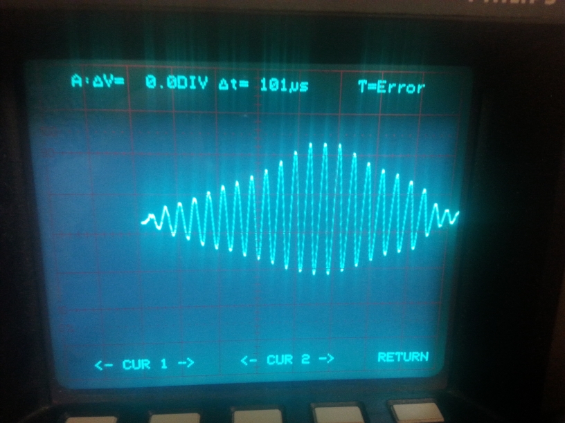
The scope is set to 10V/div AC. Its about 30 Vpp at the maximum of the decaying sinusoid.
The screenshot below shows the frequency measurement with the cursors.
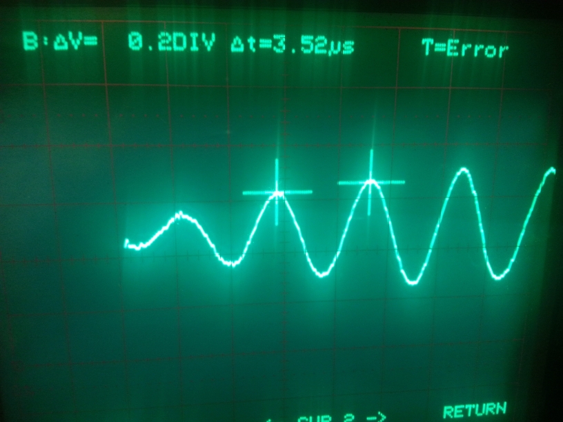
This gives a resonant frequency of about 284khz.
The screenshot below shows the red LED wirelessly lit. Its pretty bright. Thats not even full power.
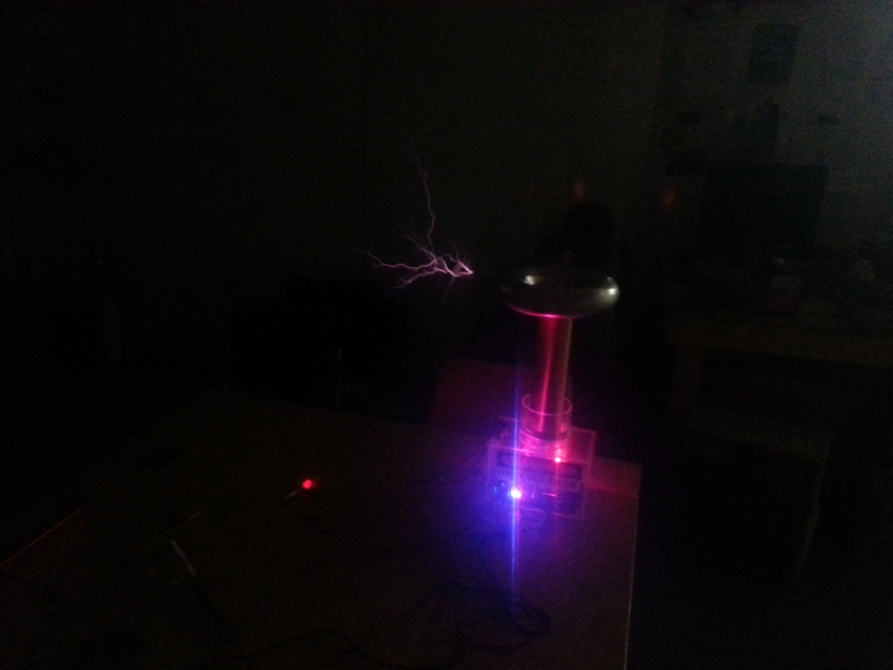
Here is a picture of my setup. The inductor is close to the tesla coil, and is collecting most of the wireless energy.I wonder if its getting energy from the primary instead of the secondary. Ideally the inductor should be above the tesla coil I think to get maximum energy. Link to picture is below.
http://onetesla.com/forum/download/file.php?mode=view&id=386
So anyway my question is: What is the power going through the 33ohm resistor? I'm getting 30 Vpp. 15V peak. The RMS is 10V. The power then is 3 watts. The current is 300mA RMS. This is the series current going through the LED. Why has the LED not burned out? I realize its a decaying sinusoid at 285khz, but if you take the true RMS value of the signal somehow it seems to me that the current is still higher than 30mA (common max current of LED).
I think I need to get the true RMS value of the voltage to find out the true power in the resistor. Maybe I should try that with a different scope or multimeter
I originally tried to make the LED circuit have the same resonant frequency as the coil, approximately 250khz, but I miscalculated and ended up with a resonant frequency of 61kHz. Ideally to collect as much energy as possible my LED circuit should be at the same resonant frequency as the tesla coil, and I will fix that later.
But anyway. I need a little advice on the results I got. I want to calculate the power across the resistor in my LED circuit. Here are the component values. R = 33ohms. L = 560uH. C = .47uF
Below is a scope screnshot of the induced voltage across the 33ohm resistor.
The scope is set to 10V/div AC. Its about 30 Vpp at the maximum of the decaying sinusoid.
The screenshot below shows the frequency measurement with the cursors.
This gives a resonant frequency of about 284khz.
The screenshot below shows the red LED wirelessly lit. Its pretty bright. Thats not even full power.
Here is a picture of my setup. The inductor is close to the tesla coil, and is collecting most of the wireless energy.I wonder if its getting energy from the primary instead of the secondary. Ideally the inductor should be above the tesla coil I think to get maximum energy. Link to picture is below.
http://onetesla.com/forum/download/file.php?mode=view&id=386
So anyway my question is: What is the power going through the 33ohm resistor? I'm getting 30 Vpp. 15V peak. The RMS is 10V. The power then is 3 watts. The current is 300mA RMS. This is the series current going through the LED. Why has the LED not burned out? I realize its a decaying sinusoid at 285khz, but if you take the true RMS value of the signal somehow it seems to me that the current is still higher than 30mA (common max current of LED).
I think I need to get the true RMS value of the voltage to find out the true power in the resistor. Maybe I should try that with a different scope or multimeter