- It is currently Thu Apr 25, 2024 12:30 pm • All times are UTC - 5 hours
Mounting the power transistors
7 posts
• Page 1 of 1
Mounting the power transistors
![]() by Vik » Thu Dec 12, 2013 2:27 pm
by Vik » Thu Dec 12, 2013 2:27 pm
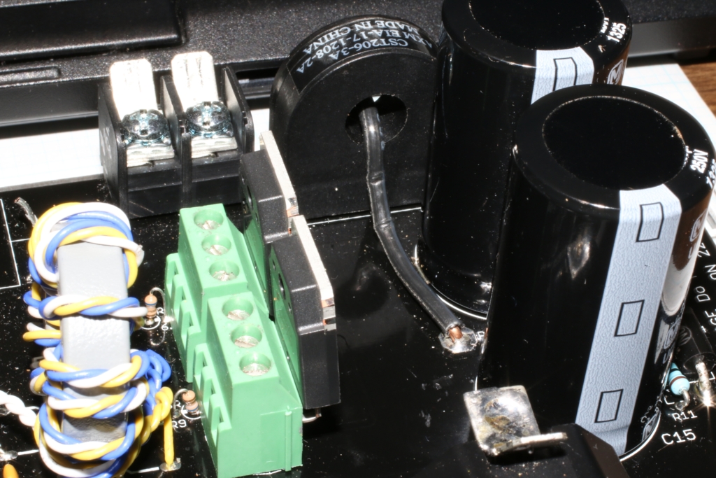
Since I seem to have to replace the two IGBT's fairly often I soldered in a couple of 3-terminal blocks. This makes it really easy to replace the IGBT's and it does not lift the heat sink too much. I used something like Digikey part number A98160-ND that I bought at the local store. People building the board might want to start off with this addition. Note that the wire going through the current transformer needs to be long enough to be pushed down out of the way of the heat sink when this is done. You have to put the two transistors in first, with the leads bent at 90 degrees and about 1/4 inch length cut off. Then you have to put the heat sink with the insulator behind the transistors and get the two screws holding them on into place... tricky the first time until you get used to it. Otherwise two separate heat sinks that don't get in the way of the screw holes in the terminal block might be nice.... but I didn't do that.
- Vik
- Tipsy Toggle Switch
- Posts: 5
- Joined: Mon Aug 26, 2013 12:52 am
Re: Mounting the power transistors
![]() by cantbeatl337 » Fri Dec 13, 2013 5:37 pm
by cantbeatl337 » Fri Dec 13, 2013 5:37 pm
I really like this idea, I am just unsure if there would be an adverse reactions to the connections. I know there is a lot of current running through pin 2 of the IGBTs and that is my only concern with not soldering it. Just seems like the connection wouldnt be nearly as good. Bayley or anyone else have thoughts on this?
- cantbeatl337
- Tipsy Toggle Switch
- Posts: 3
- Joined: Mon Nov 25, 2013 4:09 pm
Re: Mounting the power transistors
![]() by Bayley » Sun Dec 15, 2013 9:46 pm
by Bayley » Sun Dec 15, 2013 9:46 pm
I doubt it will affect performance significantly, but it will make physical reliability worse. The ring terminals also get real sketchy after a few replacements from my experience, so don't blow up the coil too many times!
-

Bayley - Lord Protector
- Posts: 1476
- Joined: Sat Jan 12, 2013 6:34 pm
Re: Mounting the power transistors
![]() by ican » Sun Dec 15, 2013 10:39 pm
by ican » Sun Dec 15, 2013 10:39 pm
This is how the three coils we've been working on have their IGBTs connected to the board as well... We only did it after having blown enough IGBTs to start worrying about burning traces by desoldering and resoldering them too many times. So far, it doesn't seem to affect performance or stress on the system much at all, and it truly makes replacing IGBTs a breeze.

- ican
- Magnificent MOSFET
- Posts: 136
- Joined: Fri Oct 25, 2013 6:15 pm
Re: Mounting the power transistors
![]() by cheeseman42 » Sun Dec 15, 2013 10:46 pm
by cheeseman42 » Sun Dec 15, 2013 10:46 pm
I did basically this same thing and it makes replacing those transistors so much less painful. Now if I could just keep them from blowing in the first place... 
- cheeseman42
- Rambunctious Relay
- Posts: 28
- Joined: Mon Aug 19, 2013 2:36 pm
Re: Mounting the power transistors
![]() by E.TexasTesla » Wed Dec 18, 2013 9:45 pm
by E.TexasTesla » Wed Dec 18, 2013 9:45 pm
If your board gets damaged you could use copper PCB vias
Go to ebay and type in "pcb vias" One seller has a 20 pack. I used option 7 which is 1.5mm ID and 2.0mm od.
They won't pull out of the board if you need to do repairs.
Go to ebay and type in "pcb vias" One seller has a 20 pack. I used option 7 which is 1.5mm ID and 2.0mm od.
They won't pull out of the board if you need to do repairs.
-

E.TexasTesla - Magnificent MOSFET
- Posts: 163
- Joined: Tue Feb 19, 2013 6:07 pm
Re: Mounting the power transistors
![]() by BubbleMan » Thu Oct 16, 2014 6:41 am
by BubbleMan » Thu Oct 16, 2014 6:41 am
Very good idea !
My board start to see some aging from IGBT soldering/desoldering.
I'll order some soon.
I notice the P/N suggested has a 3.5mm pitch spacing, while the IGBT has a 5.45mm pin pitch spacing, and also the common pitch spacing for terminal block is 5.00mm .
Does 5mm pitch fits easily on the PCB ? Is soft pin bending sufficient to install it through the PCB holes ?
I would use the 277-6072-ND as it has a low profile and has highest current rating available (20Amp) for those small terminals.
(Ref : http://www.digikey.com/product-detail/e ... ND/2513906)
Thanks.
- BubbleMan
- Tipsy Toggle Switch
- Posts: 12
- Joined: Mon Sep 29, 2014 8:29 pm
7 posts
• Page 1 of 1
Who is online
Users browsing this forum: No registered users and 3 guests