Step 1: Assemble the SD Interrupter
| R1, R10 | 10kΩ (brown black orange) |
| R2, R7, R8 | 1kΩ (brown black red) |
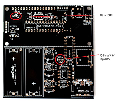
| R3, R9 | 100Ω (brown black brown) (note that on early boards, R9 is mislabeled) |
| R4 | 100kΩ (brown black yellow) |
| R5 | 3.3kΩ (orange orange red) |
| R6 | 220Ω (red red brown) |
| C1, C2, C5 | 1uF (labeled 105) |
| C3, C4 | 18pF (labeled 180) |
| D1 | 1N4148 |
| 2x Slide switch | |
| LCD headers | |
| IC1 | 7805 |
| IC2 | ATMega328 |
| IC3 | 4N25 |
| IC4 | 74HC4050 |
| IC5 | 3.3V regulator (note that early boards are mislabeled) |
| Y1 | 16MHz crystal |
| Fiber optic transmitter | |
| 2x CR123A battery holder | |
| J2 | MIDI jack |
| S1, S2, S3 | Tall tactile switch |
Heat up your iron! Let’s start soldering. We’ll begin with the SD card interrupter because we need it working to test the Tesla coil’s electronics later on.
- A. Install resistors R1 through R10. Note that in early boards, R9 is mislabeled as 1kΩ and should be 100Ω (see image below)!
- B. Install capacitors C1 through C5.
- C. Install sockets for IC2, IC3, and IC4. Align the notch on the socket to the notch pictured on the board.
- D. Install D1 and D2.
- E. Install the slide switches.
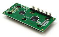
- F. Install the 16-pin female header for the LCD.
- G. Install IC1 (a 78L05 5V regulator) and IC5 (a 3.3 V regulator). See image.
- H. Install 16MHz crystal Y1.
- I. Install the optical transmitter.
- J. Install the two CR123A battery holders. Ensure that the + mark on each socket aligns with the + mark on the board!
- K. Install J2, the MIDI jack.
- L. Install the tall pushbutton switches S1, S2, and S3.
- M. Install the ICs in their sockets, taking care to orient them correctly.
- N. Solder the male header pins into the LCD module.
- O. Place the LCD module into the female header pins on the board. You don’t need to install the standoffs yet, as you should confirm that the board works before finishing the mechanical assembly.
- P. Install the batteries, taking care to orient them correctly.
 |
 Step N |

