Step 6: Low-Power System Testing
|
In this step, you will test the main board’s logic components and interrupter together at low power. Perform these steps only after you install the components in step 4, and BEFORE INSTALLING ANY POWER COMPONENTS. If you return to this step later, REMOVE THE FUSE AND COVER THE LEFT FUSE HOLDER WITH ELECTRICAL TAPE. This covers the hot lead of the holder and prevents you from accidentally touching it. Always wear safety goggles when handling an energized board! |
|
|
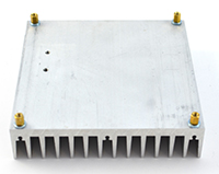
Mount the board properlyFirst, mount your board on the heat sink to ensure that it’s mechanically sturdy and not sitting on anything that may short out the pins. Fasten short M-F standoffs into the holes in the corners of the heat sink. Note that if you have M3 washers in your kit, they are to shim the standoffs and make them a little taller. Place the washers against the heat sink and screw through them. Mount the board on the heat sink and use temporary M3 6mm screws to affix them.
|

|
|
Start-up procedureStart with the driver board disconnected from all cables. First connect the interrupter using the 10 feet of optical fiber. Then, insert the IEC cable FIRST into the clover socket on the board. THEN plug it into an energized outlet. This ensures that you’re not handling the driver at the moment you plug it in. Your board is now energized. Proceed with extreme caution!
|
 
Always use extreme caution when you are working with an energized board. Wear safety glasses. |
Check for Buzzing
Turn on the interrupter and turn up the volume. You should hear the interrupter’s tone faintly produced by the gate drive transformer on the driver board. If you hear the buzz, hooray, your logic components work! If not, proceed to troubleshooting the board’s logic.
Troubleshooting the driver logic
We need to start by figuring out if the 5V and 15V supplies are functioning properly. Using a multimeter, measure across the (+) and (-) pins of the 4-pin bridge rectifier and confirm that there are about 24V. If not, first check the direction of the polar capacitors, the diodes D1 and D2, and the rectifier itself.
If these components are properly installed, we need to figure out whether one of the ICs is faulty, as a faulty IC could drag the output of the transformer down. Remove all socketed ICs, and and check for the 24V rail again. If it is still not there, there is a soldering fault on the board. Check your soldering, especially around the voltage regulators (which have fine pin spacings and are most likely to be faulty).
If removing the ICs fixes the problem, one of the ICs is faulty. Replace the ICs one by one—the one that causes the voltage to disappear is the one to replace.
After you have the 24V input working, measure the 5V and 15V rails. The most convenient places to do so are across pins 7 and 14 of the 74HCT14 (for the 5V rail) and across pins 1 and 8 of the UCC37321 (for the 15V rail). If the rails are not present, remove the ICs from their rails (the 74 series chips are on the 5V rails, the UCCs are on the 15V rails) and check if any of them are damaged in the same fashion as above.
If the rails are present and there is still no buzz, carefully check the board for bad solder joints or shorts. As a last resort, you may remove and replace the optical receiver, but keep in mind that removing this part typically destroys it, so proceed with caution.
If you have an oscilloscope, you can check Appendix A for more comprehensive troubleshooting steps.


