Step 7: Install the Power Components
| C11, C12 | 1000uF |
| D4 | Power rectifier |
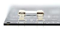
| F1 | 10A fuse and two clips |
| T3 | Current Transformer |
| P1/P2 Jumper (insert through current transformer) | |
| J110 | Jumper for 110V |
- A. If you are operating on 110V, install J110. DO NOT INSTALL THIS COMPONENT IF YOU ARE OPERATING YOUR KIT ON 220V. To populate J110, trim a piece of thick wire and strip the ends to fit the space on the board.
|
 |
- C. Install rectifier D4. Note that it is directional!
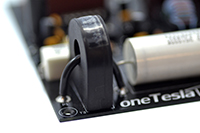
- D. Install T3, the current transformer.
|
 |
- F. Install C11 and C12, the 1000uF bus capacitors. Note their direction!
- G. Install CPRI, the primary tank capacitor.
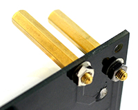
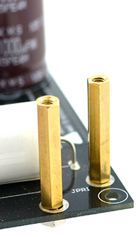
- H. Mount tall standoffs in the two holes on the PCB labeled “JPRI”. Fasten them using an M3 nut on the bottom of the PCB. These standoffs carry primary current to the resonator PCB on the top of the stack, so make sure they’re fastened securely! Use pliers or a hex wrench to tighten the nuts.
 |
 |
Z1 and Z2 are not included
Near the IGBTs there are spaces for zener TVS diodes Z1 and Z2, which are optional and not included in the kit.

