Steps 11 and 12
Step 11: Assemble the PCB Stack
In this step you will assemble the Tesla coil without its side panels. We recommend leaving off the side panels while doing your first runs and troubleshooting so that you can more easily detect any problems that may arise.
| A. Stack the driver and shield boards as shown in the image. | 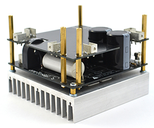 |
|
| B. Affix the secondary coil to the resonator board. If you have extra-tall bus capacitors and omitted one of the bolts, take care to orient your secondary coil properly! | 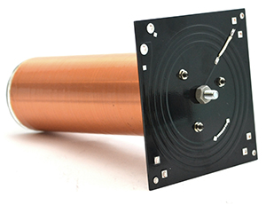 |
|
| C. Place your resonator board on the top of the stack and secure it with 6mm screws.
|
||
| D. Screw on the toroid with the M6 nut. | 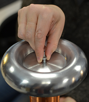
|
|
| E. Place the breakout point straight across the toroid. It should stick out about 3 inches. The breakout point should simply lay across the top, but if you want to hold it in place you can use some aluminum tape. | 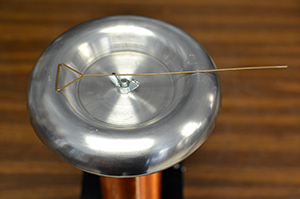 |
Step 12: Side Panel Installation
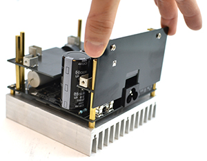
Installing the cosmetic side panels is optional. Note that due to inductive heating, they decrease performance slightly. Mount the brass angle brackets onto the side panels using a screw and nut, as shown in the photo below. To mount them to the coil, use a 6mm screw through the resonator PCB to thread into the threaded portion of the angle bracket. Also use a 6mm screw to affix the panel to the brackets on the shield board.
Note that for most kits, you will need to remove the resonator board to install the panel on the side with the IEC jack, as the PCB side panel provides strain relief for the part.
 |
 |
|
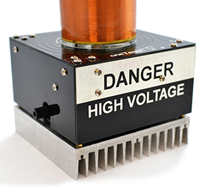 |
The completed chassis should look like this.

