Step 7: Install the Main Board's Power Components
| R2, R3 | 100kΩ (brown black yellow) | |
| C4, C5 | 47uF electrolytic capacitors | |
| X2 | .1” right-angle header | |
| D4 | 400V bridge rectifier | |
| 110V jumper | ||
| F1 | 4A 250V fuse and clips |
Before you begin this step, you should add another layer of varnish to the secondary!
In this step, install all the power components except for the IGBTs, which have a special mounting procedure.
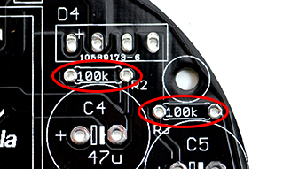
- A. Install R2 and R3. It’s very important that you install these resistors! They are bleeder resistors for the bus capacitors which drain their charge when you power off the unit. Failure to install these will result in capacitors that can’t drain their stored energy, and a board which is unsafe to service.
 |
Step A |
- B. Install C4 and C5, the bus capacitors. Note the direction! There’s a white band on the negative side, and positive is marked on the board.
- C. Install X2, the .1” 3-pin right-angle header for the primary and antenna.
- D. Install D4, the 400V bridge rectifier.
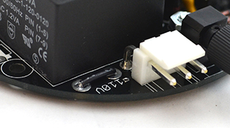
- E. If you are using a 110V kit you will need to install the 110V jumper next to the line transformer. Take the 3-inch piece of solid-core AWG 22 wire and cut it to size. Strip the ends and solder it in. If you are using a 220V kit DO NOT install this jumper.
 |
Step E |
- F. Install F1, the fuse clips and fuse. Clip the fuse into the clips to help them stay in place while soldering.

