

Thermal Analysis
Thermal analysis forms the core of DRSSTC design. Due to the extremely high peak reactive powers found in a DRSSTC, we typically do not care much about efficiency - because there are typically hundreds or thousands of KVAR circulating in the tank circuit, even low percentage losses would lead to switch destruction. Instead, we care about operating within bounds that do not permanently damage components.
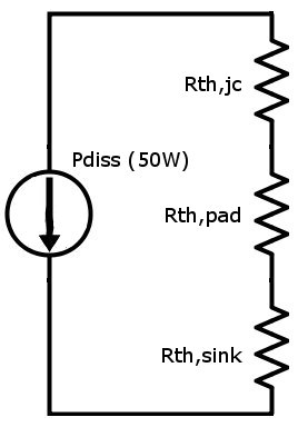
Fortunately, thermal analysis is extremely easy. We can model all thermal interfaces as resistances; these are quoted in °C/W. Heat sources (such as the dissipation from a transistor) are modeled as current sources, and the potential of an element with respect to ground (which represents the ambient temperature) gives us its steady-state operating temperature.
For example, consider the following structure:
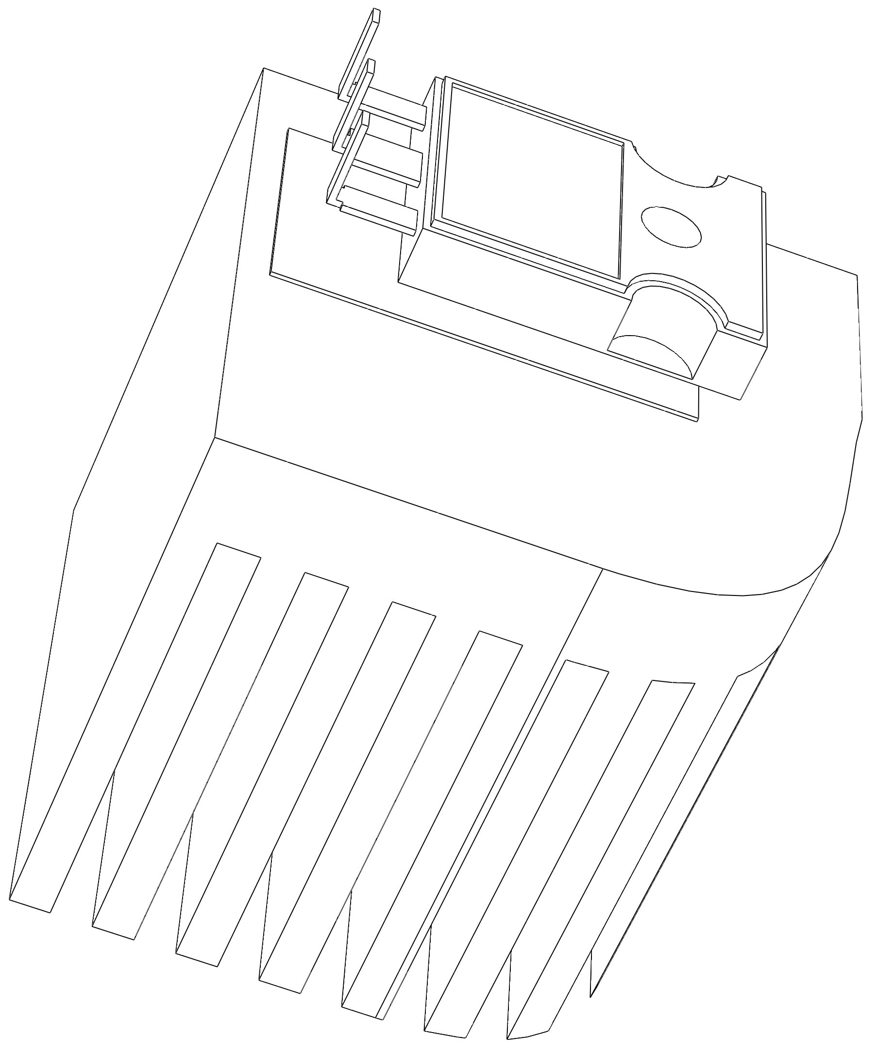
The IGBT has a thermal resistance, junction-to-case, of 1.0°C/W, the sil-pad has a thermal resistance of 0.5°C/W, and the heatsink has a thermal resistance to air of 0.8°C/W. If the IGBT is dissipating 50W, then the junction temperature rise is 50W⋅(1.0°C/W+0.5°C/W+0.8°C/W), which is 115°C. Assuming an ambient temperature of 25°C, this gives a junction temperature of 140°C. The circuit equivalent of this scenario looks like so:
The above analysis gives the steady-state temperature of a component; however, in pulsed usage, the thermal mass of a die or other component can matter. In this case, the thermal resistance of the device must be replaced by the transient thermal impedance of the device, which can usually be read from a graph on the datasheet:
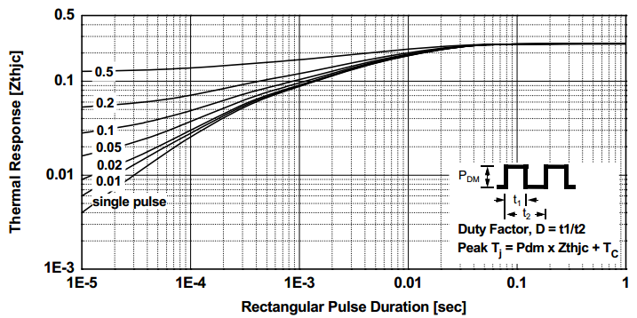
Usually, datasheets give the normalized thermal impedance; multiplying this value by the steady-state thermal impedance in the datasheet gives the actual thermal impedance for the given pulse width.