hi Gao
Yes, I know your website (this is a great job).
it is based on the Steve Ward driver.
But my transistors that explode after 5min Added use.
It is not normal !!!
If the switch is not a problem, so how can I get rid of the noise?
this is a problem of resonance frequency between the primary and the secondary ?
I noticed that the frequency of the secondary break where there is a heavy arc to the ground.
- It is currently Wed Apr 24, 2024 4:18 pm • All times are UTC - 5 hours
drsstc: the french tesla coil
16 posts
• Page 2 of 2 • 1, 2
Re: drsstc: the french tesla coil
![]() by pierrepaul » Thu Feb 04, 2016 1:46 am
by pierrepaul » Thu Feb 04, 2016 1:46 am
- pierrepaul
- Rambunctious Relay
- Posts: 28
- Joined: Wed Dec 17, 2014 1:04 pm
Re: drsstc: the french tesla coil
![]() by pierrepaul » Fri Apr 08, 2016 7:58 am
by pierrepaul » Fri Apr 08, 2016 7:58 am
Hello
I continued testing,
I tried to put a 10k resistor at the output driver UCCxxxxx
without success.
I added thermal paste on IGBT
I replaced, the secondary coil by the large screw to make high-voltage measurements. I notice that for 90 VAC, and after 2min, heat sink and the primary coil very hot (40-60 ° C)
the heat sink should be cold with too little power
I have the same result with the secondary coil, but fail IGBT after one minute show a very hot heat sink
I can not make public demonstration.
It starts to become expensive (cash)!
- pierrepaul
- Rambunctious Relay
- Posts: 28
- Joined: Wed Dec 17, 2014 1:04 pm
Re: drsstc: the french tesla coil
![]() by E.TexasTesla » Tue Apr 12, 2016 10:08 pm
by E.TexasTesla » Tue Apr 12, 2016 10:08 pm
-

E.TexasTesla - Magnificent MOSFET
- Posts: 163
- Joined: Tue Feb 19, 2013 6:07 pm
Re: drsstc: the french tesla coil
![]() by pierrepaul » Wed Apr 13, 2016 1:32 pm
by pierrepaul » Wed Apr 13, 2016 1:32 pm
thank you for the link, I will look very carefully, and I'll let you know.
Paul
Paul
- pierrepaul
- Rambunctious Relay
- Posts: 28
- Joined: Wed Dec 17, 2014 1:04 pm
Re: drsstc: the french tesla coil
![]() by pierrepaul » Thu Apr 14, 2016 5:53 pm
by pierrepaul » Thu Apr 14, 2016 5:53 pm
Hello,
after reading the document, I concluded that transistors not work well because there is an overload in the primary circuit. The current is too strong for switching IGBT.
(No detection of the transition to zero?)
So I suspect a bad frequency Raisonance I made several simulations java_tc but measures change according to the number of turns of the secondary (Insulation
Thickness), I can not do good measure.
the measurements are in centimeters
(In the simulation, java shows 458 ohms, while it is true in 260 ohms WHAT ?)
the number of secondary coil turns does not take into account insulation
Units = Inches
Ambient Temp = 16°F
----------------------------------------------------
Surrounding Inputs:
----------------------------------------------------
0 = Ground Plane Radius
0 = Wall Radius
0 = Ceiling Height
----------------------------------------------------
Secondary Coil Inputs:
----------------------------------------------------
Current Profile = G.PROFILE_LOADED
3 = Radius 1
3 = Radius 2
1.3 = Height 1
27.1 = Height 2
2031 = Turns
36 = Wire Awg
----------------------------------------------------
Primary Coil Inputs:
----------------------------------------------------
Round Primary Conductor
4.5 = Radius 1
4.5 = Radius 2
2.3 = Height 1
4.2 = Height 2
6 = Turns
14 = Wire Awg
0 = Ribbon Width
0 = Ribbon Thickness
0.068 = Primary Cap (uF)
0 = Total Lead Length
0 = Lead Diameter
----------------------------------------------------
Top Load Inputs:
----------------------------------------------------
Toroid #1: minor=5.35, major=23.51, height=28.5, topload
----------------------------------------------------
Secondary Outputs:
----------------------------------------------------
215.87 kHz = Secondary Resonant Frequency
90 deg� = Angle of Secondary
25.8 cm = Length of Winding
78.7 cm = Turns Per Unit
0 mm = Space Between Turns (edge to edge)
3190.3 m = Length of Wire
4.3:1 = H/D Aspect Ratio
458.0199 Ohms = DC Resistance
70912 Ohms = Reactance at Resonance
0.24 kg = Weight of Wire
52.281 mH = Les-Effective Series Inductance
54.173 mH = Lee-Equivalent Energy Inductance
52.1 mH = Ldc-Low Frequency Inductance
10.397 pF = Ces-Effective Shunt Capacitance
10.034 pF = Cee-Equivalent Energy Capacitance
17.532 pF = Cdc-Low Frequency Capacitance
5.95 mm = Skin Depth
8.425 pF = Topload Effective Capacitance
444.8125 Ohms = Effective AC Resistance
159 = Q
----------------------------------------------------
Primary Outputs:
----------------------------------------------------
273.54 kHz = Primary Resonant Frequency
21.08 % low = Percent Detuned
90 deg� = Angle of Primary
14.14 cm = Length of Wire
12.46 mOhms = DC Resistance
0.154 cm = Average spacing between turns (edge to edge)
0.577 cm = Proximity between coils
0 cm = Recommended minimum proximity between coils
4.978 �H = Ldc-Low Frequency Inductance
0.10919 �F = Cap size needed with Primary L (reference)
0 �H = Lead Length Inductance
119.575 �H = Lm-Mutual Inductance
0.235 k = Coupling Coefficient
0.135 k = Recommended Coupling Coefficient
4.26 = Number of half cycles for energy transfer at K
7.51 �s = Time for total energy transfer (ideal quench time)
I'll show pics of the signal that depending on the number of turns of the primary coil and the exit of the bridge using the primary
PAUL
- pierrepaul
- Rambunctious Relay
- Posts: 28
- Joined: Wed Dec 17, 2014 1:04 pm
Re: drsstc: the french tesla coil
![]() by pierrepaul » Thu Feb 24, 2022 1:48 pm
by pierrepaul » Thu Feb 24, 2022 1:48 pm
good evening
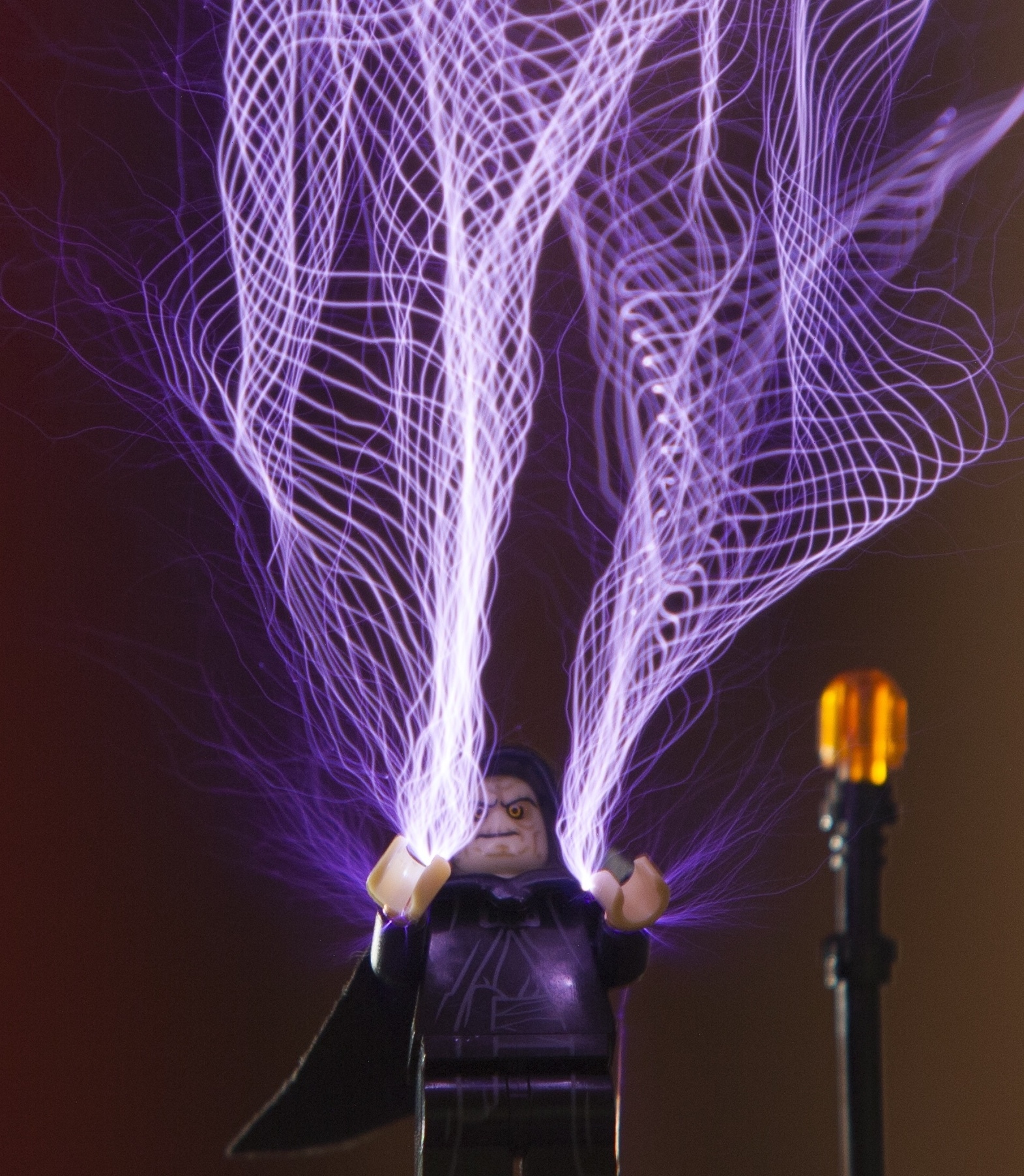
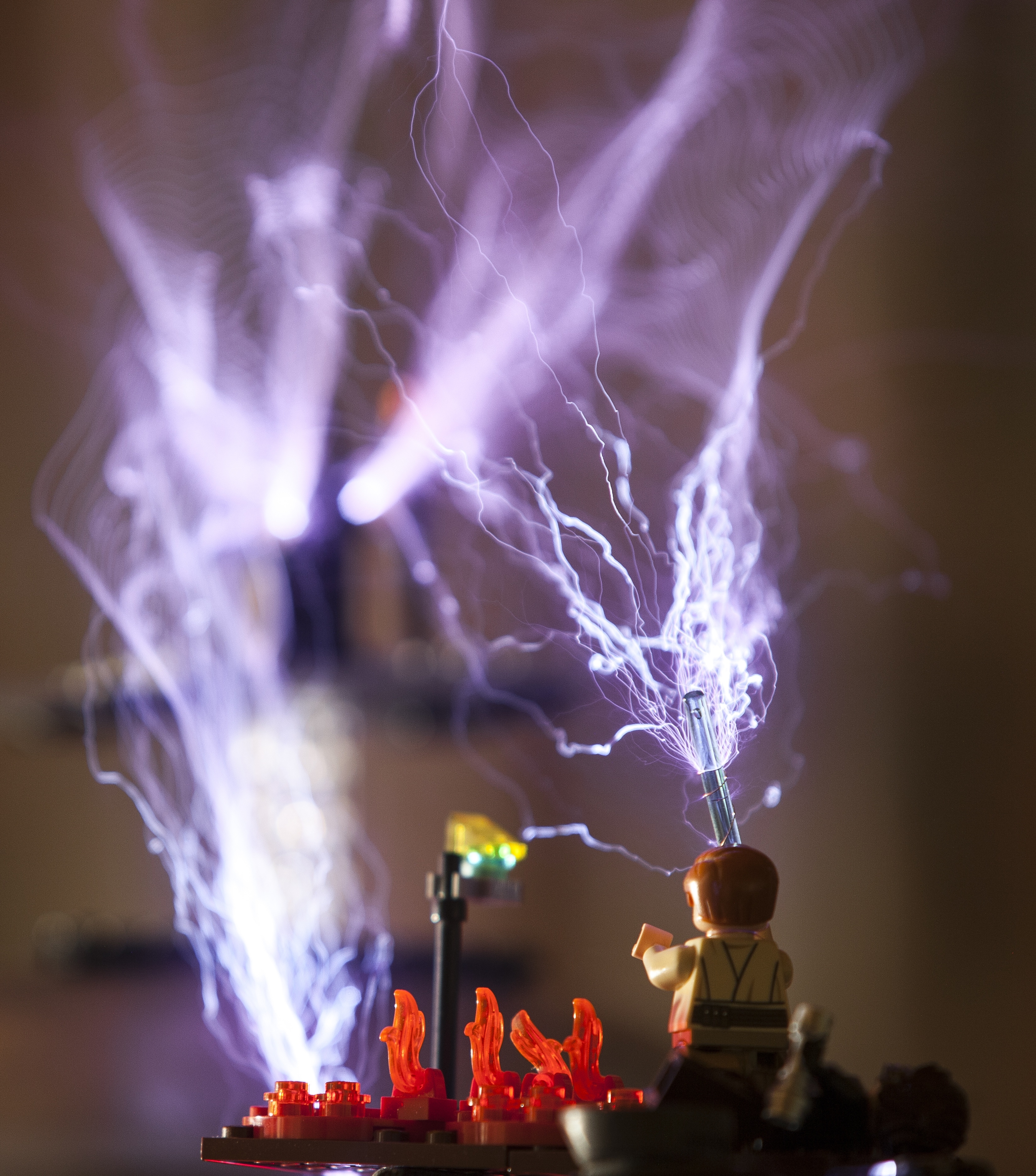
after several years of using the one tesla V1, I am publishing some photos made from lego, this may inspire you to make some artistic creations.
click on the photo to see them in full.
after several years of using the one tesla V1, I am publishing some photos made from lego, this may inspire you to make some artistic creations.
click on the photo to see them in full.


- pierrepaul
- Rambunctious Relay
- Posts: 28
- Joined: Wed Dec 17, 2014 1:04 pm
16 posts
• Page 2 of 2 • 1, 2
Return to Completed oneTesla Kits
Who is online
Users browsing this forum: No registered users and 12 guests