

Introduction to Electronics
How does the Tesla coil work?
The Tesla coil is well-known for producing extremely high voltages. In this section, we’ll explain how the oneTesla 10” coil can reach voltages over a quarter million volts using coupled resonant circuits. We’ll build up from the fundamentals, to give you a thorough explanation of what’s going on.
Current, Magnetic Fields, and Induction
Let’s start with the basics of electromagnetism. One of Maxwell’s equations, Ampere’s law, tells us that current flowing through a wire creates a magnetic field around it.

If we want to use this magentic field to our adavantage, as we do in an electromagnet, we coil the wire. The magnetic fields from the individual turns add together in the center.

A constant current makes a static magnetic field. What happens with we put a changing current through the wire? Another of Maxwell’s equations, Faraday’s law of induction, tells us that a magnetic field changing in time induces a voltage across the wire proportional to the rate of change of the magnetic field:
vinduced = -NA dB/dt
If the current is abruptly shut off, Faraday’s law tellls us that there will be a sharp spike of voltage. If an oscillating current flows through the coil, it induces an oscillating magnetic field inside it. This, in turn, induces a voltage across the coil which tends to oppose the driving current. Intuitively, the magnetic field is “stubborn,” inducing a voltage that opposes any change to the field.
Transformers
A transformer takes advantage of the law of induction to step AC voltages up or down. It consists of two coils of wire around a core. The core is soft iron or ferrite, materials which are easily magnetized and demagnetized.
![]()
An oscillating current in the primary winding establishes an oscillating magnetic field in the core. The core concentrates the field, ensuring that most of it passes through the secondary. As the magnetic field oscillates, it induces an oscillating current in the secondary coil. The voltage across each turn of wire is the same, so the total voltage across the coils is proportional to the number of turns:
N1/V1 - N2/V2
Because energy is conserved, the current on the side of the transformer with the higher voltage is smaller by the same proportion.
The Tesla coil is a very souped-up transformer. Let’s briefly consider what would happen if it were a perfect transformer. The primary winding has six turns and the secondary has about 1800 turns. The primary is driven with 340 volts, so the secondary will have 340V x 300 = 102kV across it. That’s a lot! But not quite a quarter million. Additionally, becuase the Tesla coil is air-cored and the coils are positioned relatively far apart, only a small fraction of the magnetic field produced by the primary is actually interlinked with the secondary. To understand more of what’s going on, we need to introduce resonant circuits.
Resonant Circuits
A resonant circuit is like a tuning fork: it has a very strong amplitude response at one particular frequency, called the resonant or natural frequency. In the case of the tuning fork, the tines vibrate strongly when excited at a frequency determined by its dimensions and the material properties. A resonant circuit achieves the highest voltages when driven at its natural frequency, which is determined by the value of its components.
Resonant circuits use capacitors and inductors, and therefore are also known as LC circuits. They are also known as “tank circuits,” because of the energy storage elements present.
Capacitors store energy in the form of an electric field between two plates separated by an insulator, known as a dielectric. The size of the capacitor is dependent upon the size of the plates, the distance between them, and the properties of the dielectric. Interestingly, the topload on the Tesla coil acts like a one-plate capacitor, with the ground plane surrounding the coil acting as the opposing plate. The capacitance of the topload is determined by its dimensions and its proximity to other objects.
Inductors store energy in the form of a magnetic field around a wire, or in the middle of a loop of wire. The primary inductor in the oneTesla 10” coil is six turns of AWG14 wire, and the secondary is approximately 1800 turns of AWG36 wire.
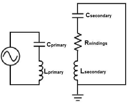
An LC circuit can have an inductor and capacitor in series or parallel. Here, we are using series LC circuits like this:

Consider what happens when you don’t drive the circuit (assume that the AC source in the above figure is replaced by a wire), but start out with the capacitor charged. The capacitor wants to discharge, so charge flows around the circuit, through the inductor, to the other plate. In the process, a magnetic field builds up inside the inductor. When the charge on each plate of the capacitor is zero, current stops flowing. But at this point, the inductor has energy stored up in a magnetic field - which tends to oppose change. The magnetic field collapses, inducing a continuing current in the same direction, thereby recharging the capacitor and restarting the cycle in the opposite direction.
The resonant frequency of an LC circuit, or the frequency at which the energy cycles between the capacitor and inductor as described above, is:
ƒo = 1/ 2pi√LC
Driving the circuit at its resonant frequency adds energy during each cycle. By providing a succession of well-timed pushes, we can build up to extremely high voltages! In the Tesla coil, a spark breaks out and discharges the circuit once the voltage is high enough.
DRSSTC
The oneTesla 10” coil employs a double-resonant topology, hence the name double-resonant solid-state Tesla coil, or DRSSTC. In a DRSSTC, the circuit driving the secondary LC circuit is another LC circuit, tuned to the same resonant frequency. In the following diagram, L1 and L2 are the primary and secondary inductors, respectively. They are weakly coupled, linking around one-tenth of their magnetic fields.
There are several reasons why Tesla coils do not employ a magnetic core. First of all, the voltages in the Tesla coil are so high that the core would quickly saturate, meaning it would no longer be magnetizable past a certain point. Also, most materials pose a resistance and heat up in a magnetic field that switches rapidly, as is the case in the coil. The high voltage the coil produces also has the potential to arc to the core. But most importantly, it’s critical that the primary and secondary coils be loosely coupled—so the secondary is not loaded down by the primary.
Half-Bridge
How do we go about exciting the primary? We use a DC voltage source, and apply the voltage in alternating directions across the primary.

The switches that we use to apply a DC voltage in alternating directions across the primary are IGBTs, short for insulated gate bipolar transistors. An IGBT is a transistor capable of controlling very high voltages and currents. This is its schematic symbol:

Its terminals are labelled collector, gate and emitter as a holdover from vacuum tubes, before the era of transistors. A simplified model of an IGBT is normally open switch that closes when a positive gate voltage (VGE) is applied.
In the following diagram of a half-bridge, S1 and S2 represent the IGBTs. They alternately turn on and off, which switches the polarity of Vbus/2 across Lprimary and Cprimary, the primary inductor and capacitor. The oneTesla 10” coil runs off a bus voltage of 340VDC.

On the control board, we get the bus voltage from rectfied and doubled line voltage.We’ll go into detail about that portion of the circuitry later.
Zero-Current Switching
When the IGBTs are fully on (the switches closed), they are nearly perfect conductors. When they are fully off (the switches fully open), they are nearly perfect insulators. When they are in transition between fully open and fully closed, or vice versa, however, they behave like resistors. Recall that the amount of power dissipated in a circuit is P=VI. If we try to switch the IGBT while the current through the circuit is large, then it will heat up a lot! We have to time the switching of the IGBTs to the natural zero-crossings of the primary LC circuit.
On the oneTesla board, we achieve zero current switching by sensing the primary current and using control logic to ensure the transistors switch at the correct times. We’ll describe this logic circuitry in a following section.
Gate Driving
The IGBTs are far from ideal switches. We want them to switch fast, to minimize the time during which they are resistive and dissipate power. The issue with switching gates fast is that they have significant internal capacitance, and it takes a lot of charge to fill up that capacitance and achieve the turn-on voltage across the gate (the voltage of a capacitor is given by V=Q/C).

To charge CGE in as short a time as possible, we want to use a short, high-current pulse. Gate drive ICs are designed to do exactly this. We use UCC3732x ICs, which can source up to 9A for brief pulses. The logic circuitry preceeding the gate drivers isn’t even close to being able to source enough current to turn the gates on fast, so the gate drivers are essential components.
Lastly, we need to isolate the gate drivers from the IGBTs using a gate drive transformers (GDT) Each IGBT needs gate voltage to be applied between its gate and emitter to turn on. This is easy on the low-side (bottom) IGBT - its emitter is always at ground, meaning its gate only needs to be brought up to +15V. Things are not so easy with the high-side (top) IGBT, because its emitter is referenced to the collector of the low-side IBGT, a node which swings between 0 and Vbus/2 (which, in our case, is 170V). This means we need to bring the gate of the high-side IGBT up to Vbus/2 + 15V to turn it on.

Fortunately, there is a simple way around this! We can drive the primary of a 1:1:1 transformer with the (bipolar) drive signal derived from a push-pull pair of UCCs.
More specifically, we drive the primary of the transformer with the difference of the outputs of an inverting and non-inverting gate driver. This ensures that half the time, this signal is positive, and half the time, this signal is negative. Due to transformer action, the voltage across each secondary of the GDT is guaranteed to replicate the voltage across the primary, no matter where we connect the ends. This means we can simply connect a secondary across the gate and emitter of each IGBT, and guarantee that Vge will always swing between 0 and 15V (regardless of the emitter’s potential).
Rectifier & Doubler

The half-bridge in oneTesla is driven by a doubling rectifier as shown in the diagram above. This rectifier alternately charges each capacitor on alternating half-cycles of the AC input, resulting in twice the source voltage across the load.
On the positive portion of the cycle, the top diode conducts and charges the top capacitor.

On the negative portion of the cycle, the bottom diode conducts and charges the bottom capacitor. The voltage across the load is the sum of the voltages on each capacitor.


Logic
As mentioned previously, control logic is necessary to sense the primary current and prevent turning on and off the IGBTs while there is current through them. Let’s step through the above schematic from left to right. (Note that the part numbers in the schematic don’t correspond to those on the board, but we use them here just for explanatory purposes. Refer to the Eagle files, available at http://onetesla.com/downloads, for the full schematic.)
The current transformer steps down the primary current to a safe level to use on the logic section of the board. R1 is a 5W resistor that loads down the transformer and limits the current. D1 starts conducting when the signal exceeds 5.7V, which is the rail voltage plus the forward voltage drop of the diode, effectively preventing the signal from exceeding 5.7V. D2 starts conducting when the signal is -0.7V. Together, D1 and D2 are protection diodes that clip the signal and prevent damage to the logic ICs if the signal from the current transformer is too high. Next, G1 and G2 are inverters which square up the signal for subsequent ICs.
The optical receiver outputs 5V or 0V depending on the signal from the interrupter. R1, R2, and R3 form a resistor network that ensure that the coil can be “tickled” into operation by just the interrupter signal on startup, in absence of a feedback waveform. When the coil is just starting up, there is no feedback signal, but the interrupter signal makes it through to the UCCs. When the coil is in operation, the feedback signal dominates the top of the signal pathway.
The inverted interrupter signal and the square wave from the squared primary current signal are then fed into a D-type flip flop, which performs logic that determines when the gate drivers recieve a signal. They are only turned on when there is a zero-crossing as well as a signal from the interrupter. The D flip-flop behaves according to the following truth table:

In our circuit, \PRE and D are pulled high. The inverted interrupter signal, which is fed into \CLR, sets \Q high when the interrupter is ON. When the interrupter turns off, \Q stays high until the next falling edge of CLK (which is synchronized with the zero crossings of the primary current), upon which it switches low.
The inverting gate driver turns on when IN is high and EN is low. The noninverting gate driver turns on when IN is high and EN is high.
Interrupter
The oneTesla interrupter is a microcontroller-based device that converts an incoming stream of MIDI commands into a stream of pulses for the Tesla coil. These pulses turn the entire coil on or off, thereby controlling both power throughput and allowing for music playback.
The MIDI commands are received through the MIDI input jack. As per MIDI specifications, the 4N25 optoisolator provides the isolation necessary to eliminate ground loops. When the microcontroller receives a note-on command, it begins output a stream of pulses at the note’s frequency. The lengths of these pulses are specified by a lookup table in the firmware. The interrupter uses separate MIDI channels to play multiple notes at once - in order to play back two channels, the software simply generates pulse trains corresponding to each channel, and then performs the OR logic function on the pulse trains before outputting them. Maximum pulse-width limitation ensures that the resulting stream does not have excessively long pulses.
Power control linearly scales the pulse widths based on the position of the potentiometer. While this does not give linear spark length, it has the advantage of predictably scaling the power consumption of the coil, a feature that would be lost if the scaling curves were tweaked for linear spark growth.
So how does it make music?
Sound is a pressure wave. Its pitch is determined by the frequency of the wave. We can make sound in a variety of ways: conventional speakers vibrate a membrane, and Tesla coils use the expansion and contraction of air due to heating from plasma.
The secondary’s resonant frequency is about 230kHz, far above the audio range. We can use bursts of sparks that are firing away at 230kHz to create pressure waves at the audio frequency. A burst of sparks fires at every peak of the audio signal. The rapid firing of the sparks is faster than your eye can resolve, so it looks continuous, but in reality the spark is forming and extinguishing at intervals of the audio frequency. This modulation technique is known as pulse-density modulation (PDM) or pulse-repetition modulation (PRM).
Current in the primary keeps increasing while the bridge is being driven. It’s important to make the bursts short enough so that the IGBTs don’t overheat. Within a single cycle, the current on the primary can reach up to hundreds of amps for a short time. Due to thermal reasons, the maximum duty cycle of the bridge is approximately 10%. The interrupter’s firmware has a lookup table of frequencies and on times, which are determined empirically by varying the pulse width and watching the spark performance.