Clarification on the Primary Circuit
Hi oneTesla! I posted this in the comments, and Kayla suggested I repost it to the forums so that everyone can share in the knowledge.
I'm really interested in the idea of a musical Tesla coil, so I'm building one in my lab! I've been using the oneTesla resources for inspiration and guidance, and I must say the documentation is extremely impressive. After about a month of fiddling with optocouplers, I finally got the interrupter board to work perfectly (well... not in running mode, but that's fine). I'm using an Arduino Mega rather than an Uno in order to support up to six notes polyphonically However, I've run into a few challenges while building the coil's primary circuit. Specifically about the images here: http://onetesla.com/driver-guide
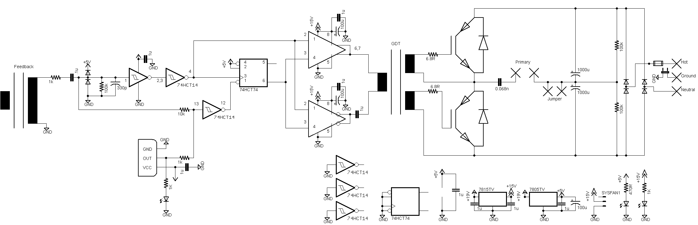
What source is connected to the current transformer T? I get that it is some sort of antenna that is responding to the oscillating E&M waves from the oscillations in the Tesla coil (in order to trigger IGBT switching at zero current crossings), but what is it *actually*. Is it a specific antenna, or just any wire in the air, or something more complicated?
Second, are the "voltage regulators" you refer to in the User Manual the same as the protection diodes, D1 and D2? Or are the "voltage regulators" something else I'm missing completely.
Third, how do G1 and G2 really work? I get that they are inverters, but I looked through the datasheet for the 74HCT14 (that's the part... right?), and I didn't see anything about squaring up the signal. I do understand, though, why it's better for the signal to be square-ish when it clocks the flip-flop and the gate drivers.
Fourth, I still am not entirely clear of the purpose of R1, R2, and R3. In the guide it says that it allows the flip-flop to be "tickled" into activation just from the interrupter signal at the start, and then still works when the top of the signal pathway is dominated by the feedback current, but why are they placed the way they are? I think I could understand this; it's just not clicking yet.
Lastly, I would like to buy a gate drive transformer, rather than build one, because without a metal toroid, I'm not confident that I can phase the transformer correctly, and that part seems pretty vital to have built correctly. That said, what specifications should I look for in a gate drive transformer (besides that the turn ratio should be 1:1:1)?
From one Tesla coil enthusiast to another, I really appreciate all your help in this endeavor.
After seeing Kayla's response, I also had another wave of questions.
1) What is the part number of the voltage regulator? Does it matter, or are we just using the diodes to clip the range of voltages that will pass to the rest of the primary circuit?
2) Can this circuit be run off of AC power (from the wall - 120V, 60Hz in America)? Do I need to run the circuit through a transformer first? (I have a 15,000V Neon Sign Transformer). Also, where does the power supply actually *go* on the circuit? It has to be somewhere on the right side of the circuit, but is it directly between the inductor and tank capacitors? Do, then, the bus capacitors act as the doubling/rectifying capacitors?
3) Kayla suggests that the primary current is routed through the 300:1 current transformer, but how do I redirect current from the primary (wherever its source is), to the left side of the circuit?
4) Finally (sorry for all the questions), is it okay if I use a breadboard for all of this? I made sure to order DIPs (well... after some struggling with hand-soldering SMT chips), but, from experience, will a breadboard be able to handle the extreme voltages and currents? I can use protoboards, but I would like to avoid soldering as much as possible.
Thank you!
-Sam
P.S. Any advice on primary coil dimensions/inductance or secondary coil dimensions, or even topload dimensions? I'm modifying a spark gap Tesla coil (which works fine - sparks ~ 6in), but I'd totally be willing to make a new Tesla coil, if it will lead to bigger sparks.
I'm really interested in the idea of a musical Tesla coil, so I'm building one in my lab! I've been using the oneTesla resources for inspiration and guidance, and I must say the documentation is extremely impressive. After about a month of fiddling with optocouplers, I finally got the interrupter board to work perfectly (well... not in running mode, but that's fine). I'm using an Arduino Mega rather than an Uno in order to support up to six notes polyphonically
What source is connected to the current transformer T? I get that it is some sort of antenna that is responding to the oscillating E&M waves from the oscillations in the Tesla coil (in order to trigger IGBT switching at zero current crossings), but what is it *actually*. Is it a specific antenna, or just any wire in the air, or something more complicated?
Second, are the "voltage regulators" you refer to in the User Manual the same as the protection diodes, D1 and D2? Or are the "voltage regulators" something else I'm missing completely.
Third, how do G1 and G2 really work? I get that they are inverters, but I looked through the datasheet for the 74HCT14 (that's the part... right?), and I didn't see anything about squaring up the signal. I do understand, though, why it's better for the signal to be square-ish when it clocks the flip-flop and the gate drivers.
Fourth, I still am not entirely clear of the purpose of R1, R2, and R3. In the guide it says that it allows the flip-flop to be "tickled" into activation just from the interrupter signal at the start, and then still works when the top of the signal pathway is dominated by the feedback current, but why are they placed the way they are? I think I could understand this; it's just not clicking yet.
Lastly, I would like to buy a gate drive transformer, rather than build one, because without a metal toroid, I'm not confident that I can phase the transformer correctly, and that part seems pretty vital to have built correctly. That said, what specifications should I look for in a gate drive transformer (besides that the turn ratio should be 1:1:1)?
From one Tesla coil enthusiast to another, I really appreciate all your help in this endeavor.
After seeing Kayla's response, I also had another wave of questions.
1) What is the part number of the voltage regulator? Does it matter, or are we just using the diodes to clip the range of voltages that will pass to the rest of the primary circuit?
2) Can this circuit be run off of AC power (from the wall - 120V, 60Hz in America)? Do I need to run the circuit through a transformer first? (I have a 15,000V Neon Sign Transformer). Also, where does the power supply actually *go* on the circuit? It has to be somewhere on the right side of the circuit, but is it directly between the inductor and tank capacitors? Do, then, the bus capacitors act as the doubling/rectifying capacitors?
3) Kayla suggests that the primary current is routed through the 300:1 current transformer, but how do I redirect current from the primary (wherever its source is), to the left side of the circuit?
4) Finally (sorry for all the questions), is it okay if I use a breadboard for all of this? I made sure to order DIPs (well... after some struggling with hand-soldering SMT chips), but, from experience, will a breadboard be able to handle the extreme voltages and currents? I can use protoboards, but I would like to avoid soldering as much as possible.
Thank you!
-Sam
P.S. Any advice on primary coil dimensions/inductance or secondary coil dimensions, or even topload dimensions? I'm modifying a spark gap Tesla coil (which works fine - sparks ~ 6in), but I'd totally be willing to make a new Tesla coil, if it will lead to bigger sparks.
