

DRSSTC Driver Guide
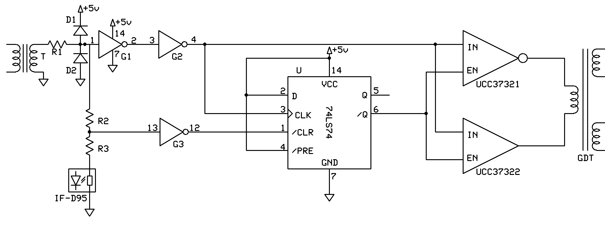
The above is a stylized schematic of the oneTesla driver. For clarity, it omits the decoupling capacitors, indicator LEDs, and power supplies.
The basic purpose of a DRSSTC driver is to generate the drive signals for the inverter, synchronized with the zero crossings of the primary current. We do this by sensing the primary current with a current transformer T. The current transformer steps down the primary current to a safe level to use on the logic section of the board. R1 is a 5W resistor that loads down the transformer and limits the current. D1 starts conducting when the signal exceeds 5.7V, which is the rail voltage plus the forward voltage drop of the diode, effectively preventing the signal from exceeding 5.7V. D2 starts conducting when the signal is -0.7V. Together, D1 and D2 are protection diodes that clip the signal and prevent damage to the logic ICs if the signal from the current transformer is too high. Next, G1 and G2 are schmitt-triggered inverters which square up the signal for subsequent ICs. The optical reciever outputs 5V or 0V depending on the signal from the interrupter. R1, R2, and R3 form a resistor network that ensure that the coil can be “tickled” into operation by just the interrupter signal on startup, in absence of a feedback waveform. When the coil is just starting up, there is no feedback signal, but the interrupter signal makes it through to the UCCs. When the coil is in operation, the feedback signal dominates the top of the signal pathway. The inverted interrupter signal and the square wave from the squared primary current signal are then fed into a D-type flip flop, which performs logic that determines when the gate drivers recieve a signal. They are only turned on or off when there is a zero-crossing as well as a signal from the interrupter. The D flip-flop behaves according to the following truth table:
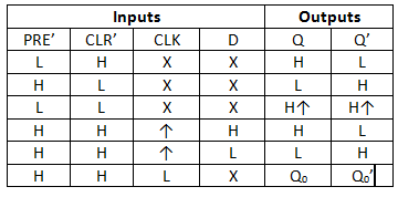
In our circuit, PRE' and D are pulled high. The inverted interrupter signal, which is fed into CLR', sets Q' high when the interrupter is ON. When the interrupter turns off, Q' stays high until the next falling edge of CLK (which is synchronized with the zero crossings of the primary current), upon which it switches low.
The inverting gate driver turns on when IN is high and EN is low. The noninverting gate driver turns on when IN is high and EN is high. The difference of the outputs of these drivers drives the primary of the isolation transformer, which drives the gates of the IGBTs.