oneTeslaTS User Manual - Table of Contents
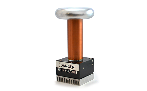
In this manual, you'll learn how to assemble and troubleshoot your oneTeslaTS Musical Tesla Coil Kit! Click on the links below to get started.
|
|
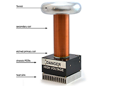
WelcomeYou’ve made a good choice with the oneTesla TS kit, the most compact and high-performing Tesla coil kit you will find. The oneTesla TS is a respin of our first, immensely popular Tesla coil kit. We’ve listened to feedback from hundreds of oneTesla v1 kit builders and redesigned the electronics and mechanical assembly with a focus on... continue >>
|

|
|
Safety WarningsElectrical Safety Warning: The Tesla coil creates extremely high voltage and high frequency sparks. NEVER TOUCH THE OUTPUT OF THE TESLA COIL. At best, you will get a nasty burn; at worst, you’ll get a potentially life-threatening shock. The Tesla coil’s control board is also dangerous while... continue >>
|

|
|
Before You BeginRead the tutorials. All of our tutorials can be found at onetesla.com/tutorials. Soldering tutorial: http://onetesla.com/tutorials/how-to-solder. De-soldering tutorial: http://onetesla.com/tutorials/how-to-desolder. How a Tesla coil works... continue >>
|
|
|
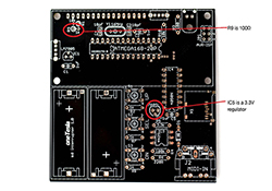
Step 1: Assemble the SD InterrupterHeat up your iron! Let’s start soldering. We’ll begin with the SD card interrupter because we need it working to test the Tesla coil’s electronics later on.... continue >>
|
|
|
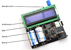
Step 2: Test the SD InterrupterPower on the interrupter. Depending on whether or not you have a micro SD card installed, you should be greeted with either “Fixed Mode” or “No SD card found” on the display. Press [Down] until... continue >>
|
|
|
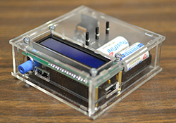
Step 3: Assemble the Interrupter Case
|
|
|
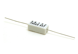
Step 5: Install the Main Board's LogicA. Install R1. Note that is a large, rectangular, ceramic, 5-Watt power resistor. B. Install R2–R6. ENSURE THAT R5 AND R6 ARE INSTALLED PROPERLY. They are two 1/2W bleeder resistors which drain the bus capacitors when the unit is powered off. Failure to install R5 and R6 properly will result in... continue >>
|
|
|
Step 6: Low-Power System TestingIn this step, you will test the main board’s logic components and interrupter together at low power. Perform these steps only after you install the components in step 4, and BEFORE... continue >>
|
|
|
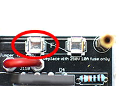
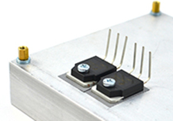
Step 7: Install the Power ComponentsA. If you are operating on 110V, install J110. DO NOT INSTALL THIS COMPONENT IF YOU ARE OPERATING YOUR KIT ON 220V. To populate J110, trim a piece of thick wire and strip the ends to fit the space on the board. B. Install the fuse clips and insert the fuse. Note that the tabs... continue >>
|
|
|
Step 8: Install the IGBTs
|
|
|
Step 10: Assemble the SecondaryFirst, solder ring terminals to the leads at each end of the secondary coil. Use fine-grit sandpaper to sand the enamel off the wire. If the end of the wire breaks, gently unravel some more. There are two endcaps: top and bottom. The bottom endcap is... continue >>
|
|
|
Step 11: Assemble the PCB Stack
|

|
|
Step 13: Tesla Coil Setup Rules
|

|
|
Step 15: General TroubleshootingA dead bridge is a dead short. If you attempt to re-test your coil right after a severe failure by simply putting in a new fuse and trying again, you’re likely to just blow the new fuse as well. A damaged bridge acts... continue >>
|

|
|
Step 16: OperationThe Tesla coil is a dangerous high voltage device. Used properly, it is an educational and fun electronics project that displays beautiful electrical arcs and lets you play with a unique form of sound creation. Used improperly, it can lead to serious injury. Always follow the directions! Treat your energized Tesla coil the same way that you would treat an open flame. You wouldn’t leave... continue >>
|

|
|
Step 17: Test Advanced Interrupter FunctionsYou will need a Micro SD card and, if you wish to test live MIDI functionality, a MIDI source for this step. A. The card must be formatted as FAT. Most small SD cards likely have this file system by default, but if you are unsure, right-click on the drive and click “Properties”. The “Filesystem” entry should read FAT, not FAT32 or NTFS. If it does not... continue >>
|

|
|
Appendix A: General Troubleshooting Tips
|
|
|
Appendix C: Oscilloscope Guide
|

