

Resonator Design
Despite its apparent simplicity, designing the primary and secondary assembly for a DRSSTC presents some challenges. We discuss these challenges in detail in this article.
Secondary Design
Begin by selecting a desired coil size and spark performance; this places the constraints on the rest of the design. Spark length dicates the necessary peak current, which in turn dictates how fast available devices can switch. For a given secondary height, increasing the diameter of the coil or reducing the diameter of the wire used will both drop the resonant frequency, as will increasing the size of the topload. Minimum wire gauge is dictated by I2R losses in the secondary; as a rule of thumb, small coils in the 500W range can get away with 40AWG, medium-sized coils should use no thinner than 30AWG, and larger coils should use 26AWG. Topload size is harder to determine; up to a point, increasing the topload size can improve spark length (since the topload stores energy, which can feed the streamer); however, increasing it beyond the optimum may result in flashover or reduced performance.
Flashover also constrains the height of a secondary; an excessively compact secondary may not be able to stand off its own output voltage on a high-performance coil. Sometimes, it may be beneficial to use a larger secondary in the interests of reliability.
JavaTC can be used to precisely calculate the resonant frequency of a given secondary assembly.
Primary Surge Impedance
Once the desired resonant frequency is known, the product LC of the primary tank components is fixed. The ratio L/C determines how quickly the primary current "rings up".
Recall that when a resonant circuit is driven at resonance, it has zero impedance. Should the primary reach a steady state, it would have current circulating in it limited only by the ESR of its components. To avoid this, we interrupt the drive power after a certain period of time. The surge impedance √L/C determines how quickly this current rings up. A low impedance tank is typically desirable for large, low-frequency coils; it allows for as much energy as possible to be transferred within a few cycles of oscillation, which results in long streamers with low average power consumption. A tank capacitance of around 200nF is typical for medium and large DRSSTCs.
On smaller coils, a high-impedance tank may sometimes be desirable. Otherwise, it may be hard to have enough average power throughput for reasonable interrupter frequencies, as the low impedance places limits on the maximum allowable pulse length. This may result in reduced performance; while peak power plays a greater part in determining spark length, sufficient average power is needed as well (to, among other things, maintain a hot ion channel).
Knowing the desired surge impedance lets us determine fully the primary capacitor value and primary coil inductance.
Primary Capacitor
The primary capacitor should be a polypropylene film capacitor. Polyester, mylar, and paper are not acceptable alternatives, as their higher dielectric losses will cause heating and failures.
The design of a primary capacitor is usually constrained by the builder's budget. Ideally, the AC voltage, peak current, and RMS current limits given by a capacitor's datasheet would be followed; in reality, this would result in a capacitor costing several hundred to several thousand dollars. Instead, coilers typically design using the DC voltage rating of the capacitors, then parallel enough strings to acheive the desired capacitance. This usually gives a reasonably reliable capacitor. Modern self-healing technologies ensure that capacitor failures do not occur; instead, wear and tear manifest themselves as a slow, gradual reduction in capacitance.
The requisite capacitor voltage can be easily found given the capacitance and peak current; this voltage is given by 2πfCIpeak. Using more, lower-voltage capacitors of the same family in series will result in a more robust capacitor (as the difference between DC and AC voltage ratings is smaller for lower voltages):
However, such a capacitor is typically more expensive and bulkier than a capacitor made from fewer, higher voltage capacitors.
Recommended lines of capacitors include:
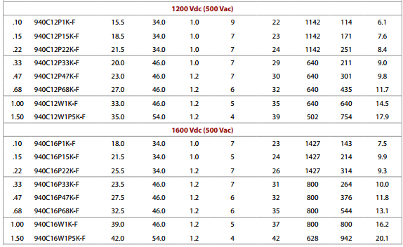
- Cornell Dubilier 942C and 940C series. The 942C series are hybrid film/foil capacitors; the 940C series are standard metallized film capacitors. The 942C is extremely scalable; anything from small tabletop coils to 20KW coils can be built by seriesing and paralleling enough of these capacitors. The 940C is typically only used in smaller coils, as its pure-metallization construction renders it less abuse-tolerant than its larger brothers in the 942C series.
- Eurofarad SP2550 series. Extremely hard to find new, but readily available on the surplus market. These capacitors are giant film/foil capacitors, capable of handling 150Arms at 600Vrms. Their DC rating is generally around 1000V, with breakdown happening around 1200V. Only applicable for large coils due to the high (3.75μF) capacitance, but significantly cheaper than a bank of Cornell Dubilier capacitors of the same rating.