
tinyTesla User Manual - Table of Contents

In this manual, you'll learn how to assemble and troubleshoot your tinyTesla Musical Tesla Coil Kit! Click on the links below to get started.
|
|
WelcomeWith tinyTesla you’ll learn about electronics, flex your soldering muscles, shoot lightning and play music using electricity! A Tesla coil is a device that uses resonant circuits and alternating current to produce extremely high voltages. Originally invented by Nikola Tesla... continue >>
|

|
|
Safety WarningsAdult Supervision Required. Users under 18 should only use this kit under the supervision of an experienced adult. Pacemaker Warning. Persons with electronic medical implants such as pacemakers should not... continue >>
|

|
|
Before You BeginRead the tutorials. All of our tutorials can be found at onetesla.com/tutorials. Soldering tutorial: http://onetesla.com/tutorials/how-to-solder. De-soldering tutorial: http://onetesla.com/tutorials/how-to-desolder. How a Tesla coil works... continue >>
|
|
|
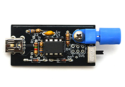
Step 1: Assemble the InterrupterThe interrupter is the Tesla coil’s music controller. It connects via a mini USB cable to a computer, and appears as a MIDI device. Assemble it first because you will need to use it to ensure the low-voltage side of the main driver board is working. The interrupter is also... continue >>
|
|
|
Steps 2–3: Troubleshoot the Interrupter
The interrupter is powered over USB and can be controlled using our 1T Panel software available for download at onetesla.com/downloads. You will need a mini USB cable to connect to the interrupter. It behaves like a MIDI device and... continue >>
|
|
|
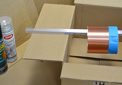
Step 4: Varnish the Secondary
|
|
|
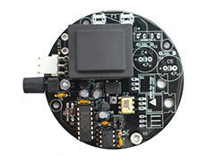
Step 6: Install the Main Board's Logic ComponentsWe’re splitting up the main board assembly process into two steps so that you can clearly see which components are related to the main board’s logic vs. its power. If you wish, you can troubleshoot the main board’s logic after this step to ensure that your construction is correct so far, but you can also install it all at once and... continue >>
|
|
|
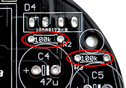
Step 7: Install the Main Board's Power ComponentsBefore you begin this step, you should add another layer of varnish to the secondary! In this step, install all the power components except for the IGBTs, which have a special mounting procedure. A. Install R2 and R3. It’s very important that you install these resistors! They are bleeder resistors for the bus capacitors which drain their charge when you power off the unit. Failure to install these will result in... continue >>
|
|
|
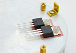
Step 8: Install the IGBTsThe IGBTs have a special mounting procedure. They are mounted flush against the heat sink and soldered to the top of the board, not the bottom like the rest of the components. A. Ensure that the surface of the heat sink is clean. If there is any grease or grime, clean it away using... continue >>
|
|
|
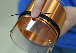
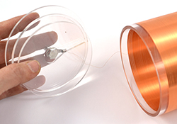
Step 9: Wind the Primary
|
|
|
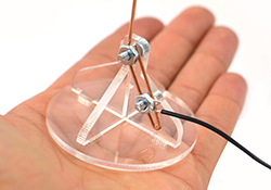
Step 11: Assemble and Attach the Antenna
|
|
|
Step 13: Assemble the End CapA. Build the end cap for the secondary according to the diagram. Don’t worry if it’s not pretty—remember that with the toroid mounted, you don’t see the end cap! DO NOT glue down the bolt in the cap. The bolt should be a little loose because when... continue >>
|
|
|
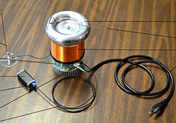
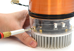
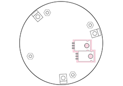
Step 14: Mount the Secondary, Toroid, and Breakout PointA. Place the secondary tube over the main board, orienting the notches appropriately. Use M3 screws to mount the tube. Don’t over-tighten! B. Plug in the primary coil connector. C. Mount the toroid onto the secondary tube and fasten it using... continue >>
|
|
|
Step 15: Full-System TroubleshootingDo a Thorough Check. First do a visual inspection of your board. The vast majority of problems are caused by faulty component installation, which can be caught before you apply power to the coil. Thoroughly check the following... continue >>
|
|
|
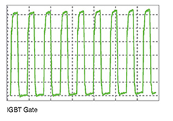
Step 16: In-Depth TroubleshootingIf your coil is under-performing or not turning on and you want to do some detailed troubleshooting, read on. You can also perform these steps if you want to verify that your coil is constructed properly before powering it up fully, such as when you’re waiting for your secondary’s varnish to dry. A. Check for GDT Buzz. Verifying whether you can hear the gate drive transformer vibrate at... continue >>
|
|
|
|
Step 17: OperationRules. The Tesla coil is a dangerous high voltage device. Used properly, it is an educational and fun electronics project that displays beautiful electrical arcs and lets you play with a unique form of sound creation. Used improperly, it can lead to serious injury. Always follow the directions! Treat your energized Tesla coil the same way as... continue >>
|
|
|
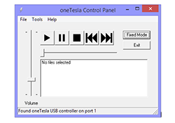
Appendix A: Guide to 1T Panel1T Panel is a Windows program that sends MIDI commands, and is designed for ease of controlling any oneTesla interrupter, particularly tinyTesla’s interrupter which is controlled over USB. Download 1TPanel at onetesla.com/downloads. 1T Panel features... continue >>
|
|
|
Appendix B: Diagrams
|