Step 16: In-Depth Troubleshooting
If your coil is under-performing or not turning on and you want to do some detailed troubleshooting, read on. You can also perform these steps if you want to verify that your coil is constructed properly before powering it up fully, such as when you’re waiting for your secondary’s varnish to dry.
A. Check for GDT Buzz
Verifying whether you can hear the gate drive transformer vibrate at the interrupter frequency will help you narrow down your problem to the board’s logic vs. the board’s power components or the resonator.
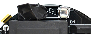
- i. REMOVE THE FUSE and cover the left fuse holder with electrical tape. Removing the fuse de-energizes the power side of the board. This fuse clip becomes electrically hot when you plug in the board to AC power, so you want to cover it with tape to prevent yourself from accidentally touching it.
Remove the Fuse to Separate Logic and PowerWhen debugging, you want to separate your board’s logic from its power components. Always remove the fuse and cover the fuse clips in electrical tape! |
 |
- ii. Start up the coil following the startup and shutdown procedure in step 15. Verify correct operation of your interrupter, then connect your interrupter to the coil, then connect your AC adapter to your coil, then plug in the AC adapter.
- iii. Play a tone or song using the interrupter and listen closely to the board. You should hear the tone playing faintly from the GDT. Note that it’s a faint sound, so you need to be in a quiet environment!
If the GDT is buzzing then your board’s logic half is most likely working. The problem lies in the power components, the antenna connection, or the resonator.
Every problem has a cause!
Remember that every problem has a cause. Components are very rarely dead upon arrival. Blindly replacing chips can lead to a whole lot more dead chips if you don’t find the root cause!
B. Check for Warm Spots
You can learn a lot without even pulling out your multimeter from checking whether components on the board get hot.
Once your board is unplugged and you have waited for 5 minutes to allow the bus capacitors to discharge, check whether the ICs or regulators are hot. If an IC is hot, it could be damaged. If the 5V regulator is hot, then you know that a component that is powered off of 5V has failed short, or there’s a solder bridge that’s causing a short along the 5V rail. The same thing goes for the 15V regulator. If you remove the suspected IC and the regulator is still hot, you know that either the regulator is damaged or you have a solder joint. It’s possible that the IC was damaged as well.
If an electrolytic capacitor is hot, it’s installed backwards. Don’t touch the tops of the bus capacitors (47 uF) if their tops are metal! If you didn’t install your 100kΩ bleeder resistors properly or didn’t wait long enough, they may still be energized!
What's a "voltage rail?"
The 5V and 15V rails are all the points on the circuit board that should be at 5V and 15V, respectively. They’re commonly called “rails” because these points are connected to each other, they all carry the same voltage and they all supply power to components that need 5V or 15V.
C. Troubleshooting with a Multimeter
 |
Disassemble the coil down to just a driver board mounted on a heatsink. REMOVE THE FUSE and cover the left fuse holder with electrical tape. Removing the fuse de-energizes the power side of the board. This fuse clip becomes electrically hot when you plug in the board to AC power, so you want to cover it with tape to prevent yourself from accidentally touching it.
|
|
 |
|
You will need to have your board plugged in. Use extreme caution when working on an energized board! Wear safety glasses.
|
Using a multimeter, you will measure the logic rails to confirm that they are working. For the next few tests, ground the black probe of your multimeter to the (-) pin of the low voltage rectifier (D3) and use the red probe to measure the pins in question.
- Rectified input, ~22V: (+) pin of D3
- 5V rail: Pin 14 of the 74HCT14
- 15V rail: Pin 8 of UCC27425
If there is no AC input, D3 is suspect and may need replacement. If AC input is low, there is probably something wrong downstream—chances are one or both of the logic rails will also be low or absent.
If either logic rail is incorrect, remove the ICs and check again. If this results in all rails working, you either have a dead IC, or a damaged regulator that is incapable of supplying current. You should replace the IC of which removal caused the rails to reappear, or, if you want to be safe, all the ICs.
If removing the ICs doesn’t restore the rails, check for solder bridges on the board. If there are no solder bridges, try replacing the corresponding voltage regulator. If the rails are all present but the coil doesn’t buzz (and your soldering checks out), you probably have a damaged IC. If you have an oscilloscope, you can use the next section to determine which ICs need to be replaced. Otherwise, we recommend replacing both ICs for simplicity’s sake. There is also a chance that the optical receiver is damaged.
D. Debugging with an oscilloscope, function generator, and power supply
Start by soldering a (preferably black, to indicate ground) wire to the (-) pin of D3. This will act as your ground for all subsequent tests. Solder a wire of a different color to the (+) pin of D3. These wires act as your power inputs for testing. Set your power supply to ~18V and connect the supply to the wires you just soldered in.
As before, remove the fuse and cover the left fuse clip in electrical tape. Plug in the board. Set the interrupter for Fixed mode, max frequency, and max power, and connect it to the coil.
Download the Schematics
Schematics and pictures of the board are available at onetesla.com/downloads.
Test for startup pulses
The signal pathway is:
Antenna → pin 13 of IC2 → pin 12 of IC2 → pin 11 of IC2 → pin 10 of IC2 → pins 2 and 4 of IC5
and
Center pin of IC1 → pins 1 and 6 of IC5
The outputs of the gate drive IC (pins 5 and 7) are the AND’ed results of pin 1 and pins 2 and 4, respectively—this should be a 15V signal as shown in the images below. If it is, you can proceed to the next step. Otherwise check the following:
- If there is nothing on pin 6 of IC5, check your soldering for shorts and/or replace the fiber receiver.
- Check the signals on the gate driver. Pin 6 should be 15V, and the inputs and outputs should match the figures below. If there is input and voltage but no output, replace the IC.
- Check pin 14 of the 74HCT14 ICs for power. If none is present refer to the steps in the previous section for absent 5V rail.
- Pins 11 and 13 of IC1 are the inputs of inverter gates, and pins 10 and 12 are their outputs, respectively. If the outputs are not correct, check all components downstream from it for soldering errors and other faults. In particular, there should be a signal on the gate driver inputs if the gate driver is removed. You can use this to check the state of the upstream electronics.
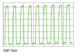
- If the gate driver’s output voltage measure between pins 1 and 3 of each IGBT, the waveform should be as below. If it is not, make sure you soldered T2 properly and didn’t forget R1 or C8. If that is the case you have dead IGBT gates and you should replace Q1 and Q2.

Once you have proper startup pulses at the gates of Q1 and Q2, connect your signal generator to ground and the top of the antenna, and set it for a 0-5V 300KHz 50% duty cycle square wave. You should hear the buzzing stop. Scoping the gates of the transistors should give you the following waveform:

In the unlikely case that doesn’t happen, check your 15V rail—if it is not 15V you have a damaged regulator incapable of outputting current. In addition, check D1 and D2 for orientation, and IC2 for proper installation.

