Step 8: Install the IGBTs
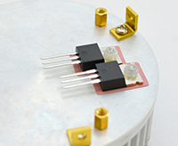
The IGBTs have a special mounting procedure. They are mounted flush against the heat sink and soldered to the top of the board, not the bottom like the rest of the components.
- A. Ensure that the surface of the heat sink is clean. If there is any grease or grime, clean it away using rubbing alcohol.
- B. Using the outline in Appendix B as a guide, place the sil-pad on the heat sink. Place the IGBTs on the sil-pad and use nylon screws to hold them in place.
 |
Step B |
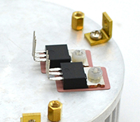
- C. Using pliers or your fingers, carefully bend the IGBTs 90 degrees at the point where the legs become thinner.
 |
Step C |
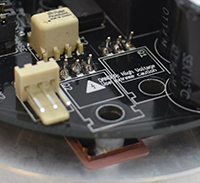
- D. Place the board over the IGBTs and position it so that the leads pass through the holes in the board. This should be easy if you have the IGBTs rotated at the correct angle, but can be tricky if they are not properly aligned.
 |
Step D |
- E. Screw down the board into the standoffs, so that it is mechanically secure. You may need to force the leads to bend a little bit to get the board to align to the standoffs. You want everything mechanically secure before soldering, so that you don’t put stress on the soldered joints.
- F. Double-check that that your IGBTs are not touching each other, and that they are not touching the heat sink. Tighten the nylon screws if needed.
- G. Solder in the IGBTs on the top of the board. You may find it easier to remove the IGBTs later if you leave the leads long. In the case of a problem, the IGBTs are usually the first part to fail, so if you stress your coil it’s likely that you will be replacing them!

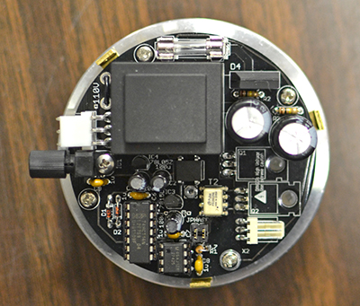
The completed board.

