
Appendix C, D, and E
Appendix C: Oscilloscope Guide
The oneTesla TS kit can be built without an oscilloscope. However, having a scope can be of great assistance in debugging. The following pages provide snapshots of key waveforms, along with tips for debugging the coil.

|
During startup (before the coil starts oscillating, e.g. when the primary is not connected), the waveform at pin 6 and 7 of IC3 and IC4 should look like this. | |

|
Across the gate and emitter (pins 1 and 3) of either IGBT the waveform should look like this. | |

|
This waveform is on many pins, with an amplitude of 5V. It should be on pins 1, 4, and 13 of the 74HCT14, pin 3 of both UCC chips, and pin 3 of the 74HCT74, as well as the output pin (center pin) of the optical receiver. | |

|
This waveform is on many pins, with an amplitude of 5V as well. It should appear on pins 3 and 12 of the 74HCT14, and pin 2 of the 74HCT74. | |

|
5VDC should be present on pins 2, 4, and 6 of the 74HCT74. | |

|
This waveform should be on pins 7 and 8 of the UCC37321, and between the gate and emitter of both IGBTs during oscillation. | |

|
This is what the primary current should look like during oscillation. |
Appendix D: Further Resources
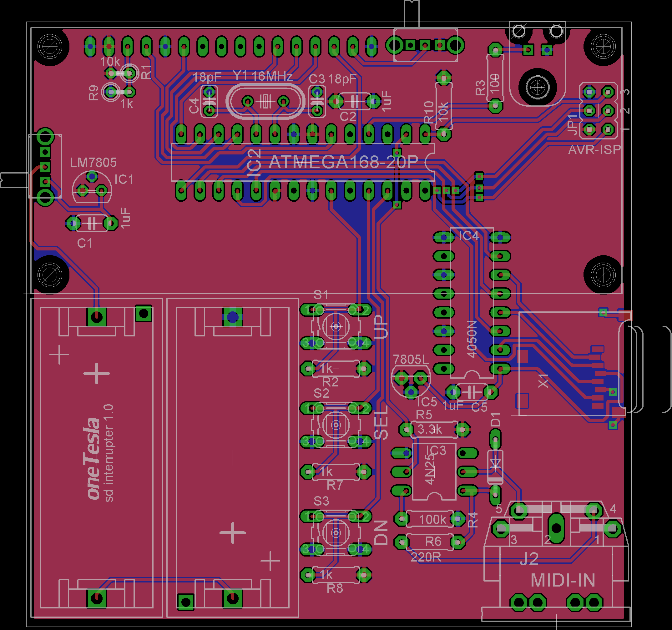
Schematics and Board Images
Download schematics and board layout images at onetesla.com/downloads.
Part Data Sheets
Don’t be afraid to look at the documentation of individual parts if you want to understand more about how they work. Read the descriptions in the data sheets and take a look at the part pinouts, especially if you are doing detailed troubleshooting on your driver.
oneTesla Resources
As you’ve probably already noticed, replacement parts are available on our website and help is available at onetesla.com/forum.
Appendix E: Board schematics