Steps 8 and 9
Step 8: Install the IGBTs
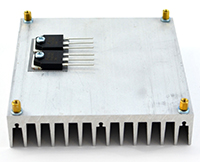
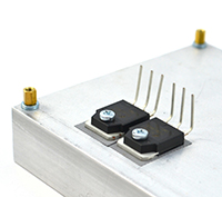
The IGBTs are mounted flush against the heat sink, and their leads are soldered to the top of the PCB. Sil-pad is an electrically insulative but thermally conductive material, which allows heat from the IGBTs to be transferred to the heat sink to dissipate, but insulates it electrically.
- A. Clean the surface of the heat sink in the area of the IGBTs thoroughly. Make sure there’s no dirt or grime.
|
 |
|
|
 |
|
|
||
|
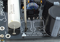 |
- F. Solder in the IGBTs. You can clip the leads or leave them long, which may make them easier to remove later on.
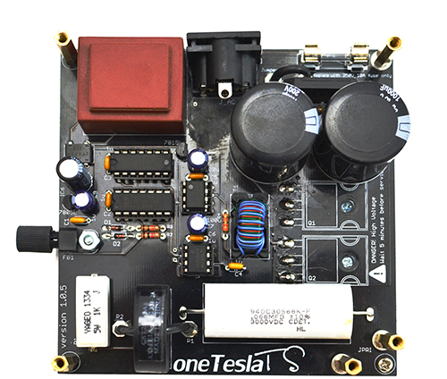
The completed board
Step 9: Finish soldering the PCBs
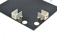
The shield PCB has a conductive mesh that shields the electronics of the driver from the strong magnetic field produced by the primary coil directly above it. The only parts on this board are solder-in M3 brackets to which you will later fasten the PCB side panels.
 |
 |

